The Build
Warning
This project involves modifying equipment that plugs into a wall outlet (120VAC or more depending on your location) and can draw a lot of amps - meaning mistakes could kill you. If you don't know how to work safely with such equipment, get help from someone who does.
My design is the same as PaulV's with a few minor modifications. I suggest you refer to his blog for more information.
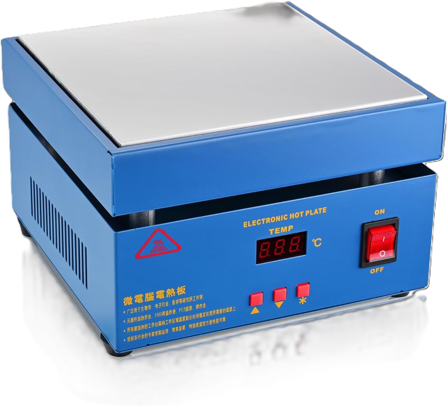 This is the hotplate I started with. It was described with the following word jumble: "Upgraded 110V 850W
Soldering Hot Plate LED Microcomputer Electric Preheat Soldering Station Welder Hot Plate Rework Heater Lab
200X200mm Plate" (as is typical with such products). Since this apparently had a higher wattage than PaulV's
model, I was hopeful that no additional heater elements would be required. And it does seem to work fine.
This is the hotplate I started with. It was described with the following word jumble: "Upgraded 110V 850W
Soldering Hot Plate LED Microcomputer Electric Preheat Soldering Station Welder Hot Plate Rework Heater Lab
200X200mm Plate" (as is typical with such products). Since this apparently had a higher wattage than PaulV's
model, I was hopeful that no additional heater elements would be required. And it does seem to work fine.
Parts
Since this was a one-off build for me, I decided to build it on perfboard rather than designing a PCB.
I also decided to use a number of prebuilt modules to make the build easier. These modules are attached
to the perfboard using headers (sockets). This has the benefit of making the build simpler and replacement
of a module easy.
Here is a list of parts I used (I've listed my source for parts in some cases but inventories change so you may have to hunt around). For parts I purchased from Amazon, I've shown the description as it appeared on Amazon so you can (maybe) look it up. I'm not providing links because, again, inventories seem to change rapidly:
| Part | Description | Purchased From |
|---|---|---|
 |
A piece of perfboard 150mm long and 54.5mm high. I don't have a photo of the empty perfboard but here it is shown with the sockets and a few of the wires installed.. | |
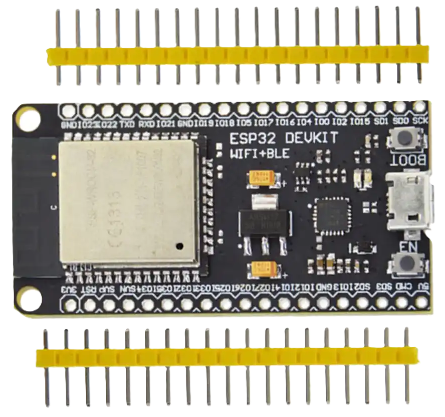 |
ESP32 Devkit based on the ESP-WROOM-32 module. 520kB SRAM, 4MB flash. CP2104 USB-to-UART for programming. | universal-solder.ca |
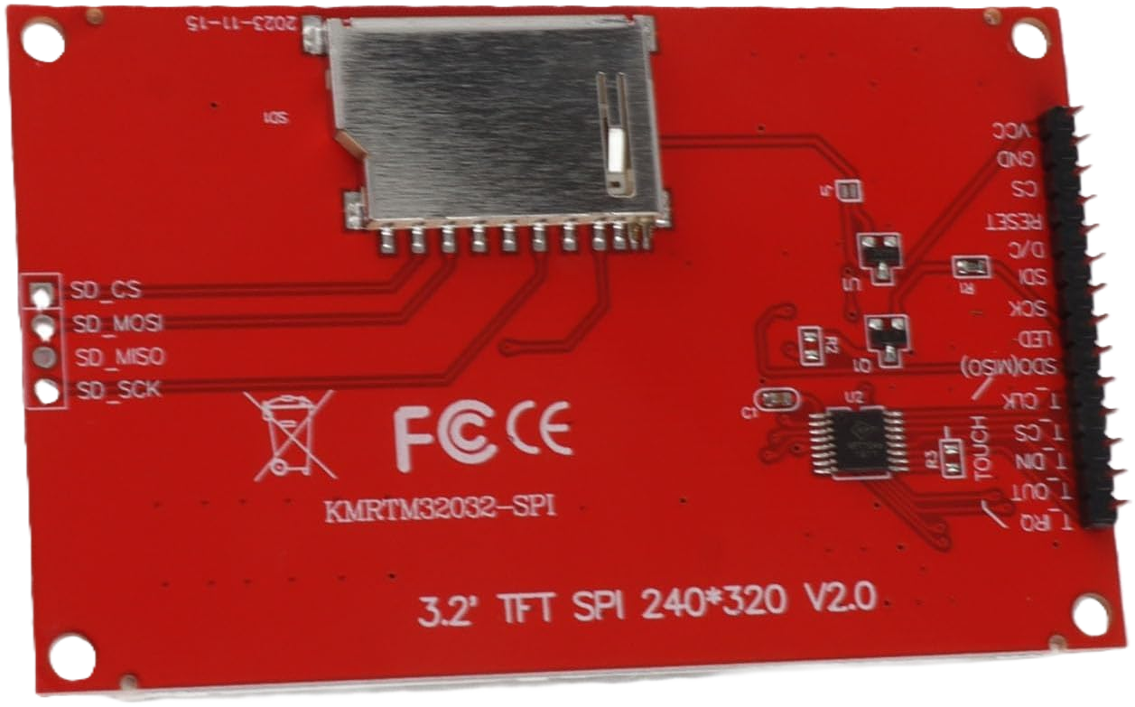 |
3.2 Inch 240x320 TFT LCD display with 4-wire SPI interface. Mine uses the ILI9341 driver IC. This display has touch screen capability but the touch screen is not used. I replaced one of the male headers with a 90 degree header to make it fit the enclosure I used. |
Amazon |
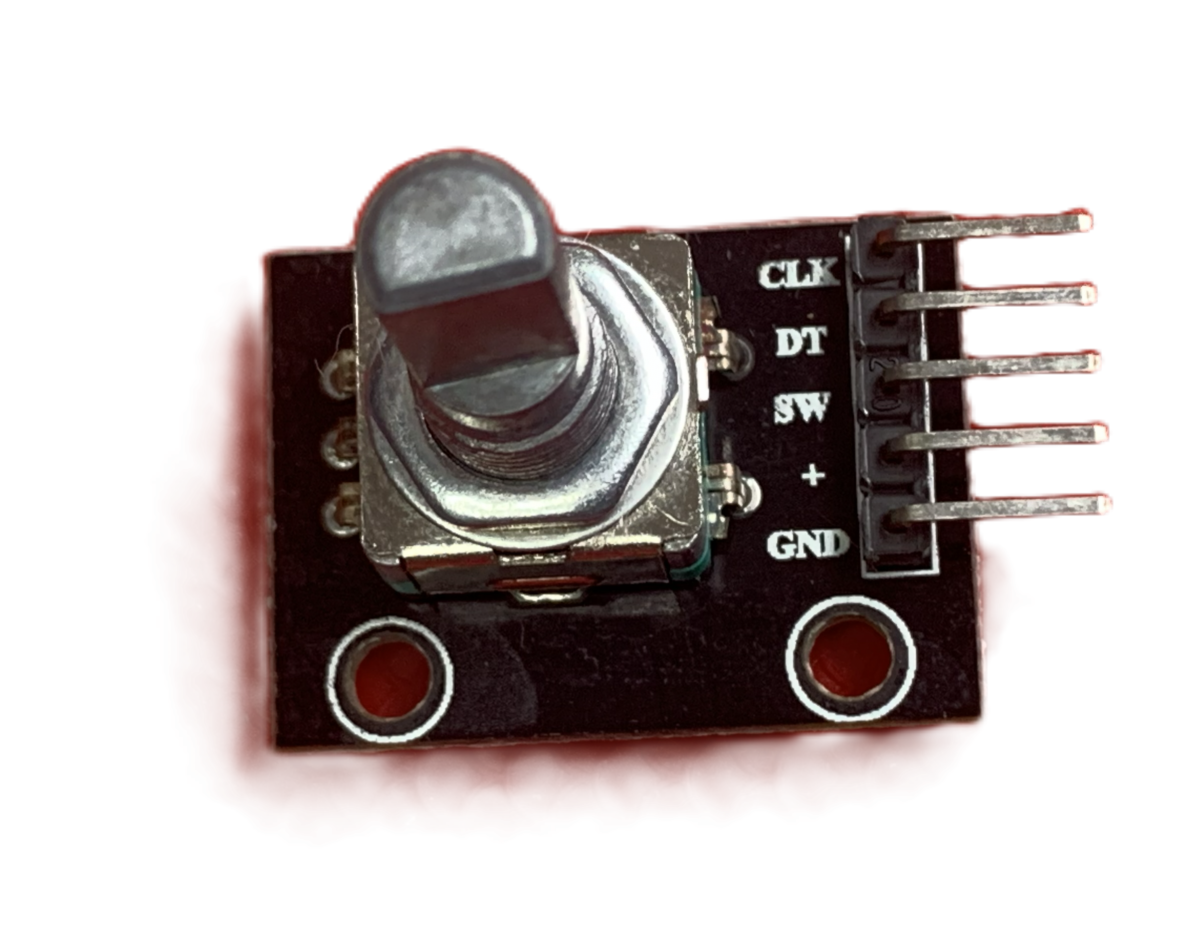 |
5 Pin rotary encoder and matching knob. | |
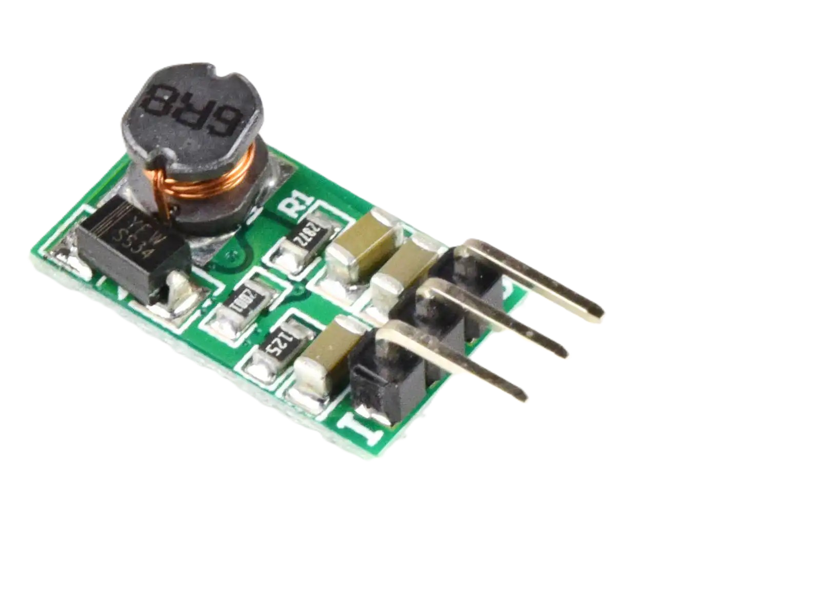 |
5V 1A DC-DC Buck converter, pin compatible with 7805 but more efficient. | universal-solder.ca |
|
3.3V 1A DC-DC Buck converter, pin compatible with 78033 but more efficient | universal-solder.ca |
3 x 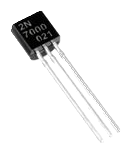 |
2N7000 N Channel MOSFET | Mouser |
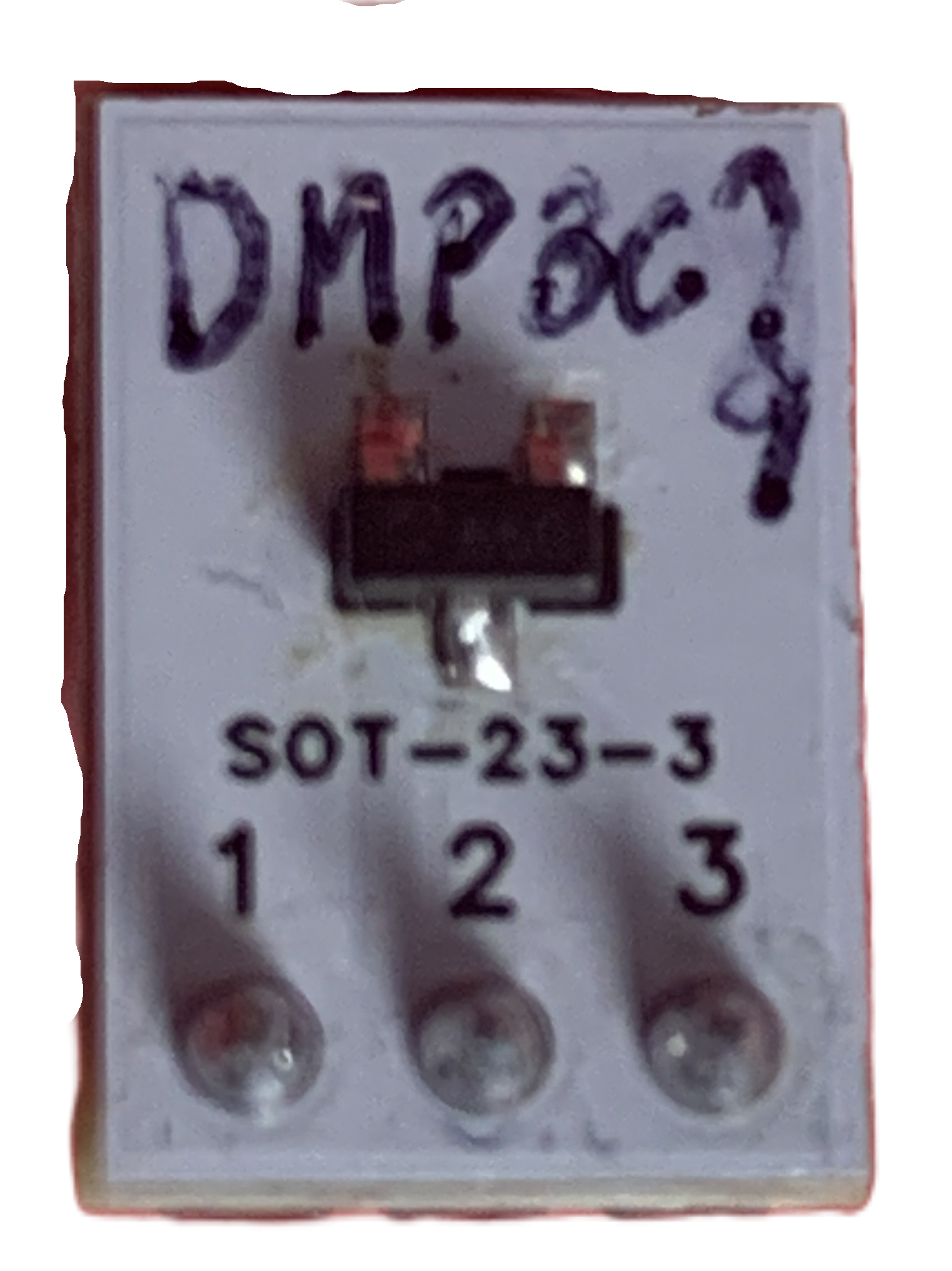 |
DMP3099L-13 P Channel MOSFET. Because this is an SMD part, I mounted it on a breakout board with a 3 pin male header. | Mouser |
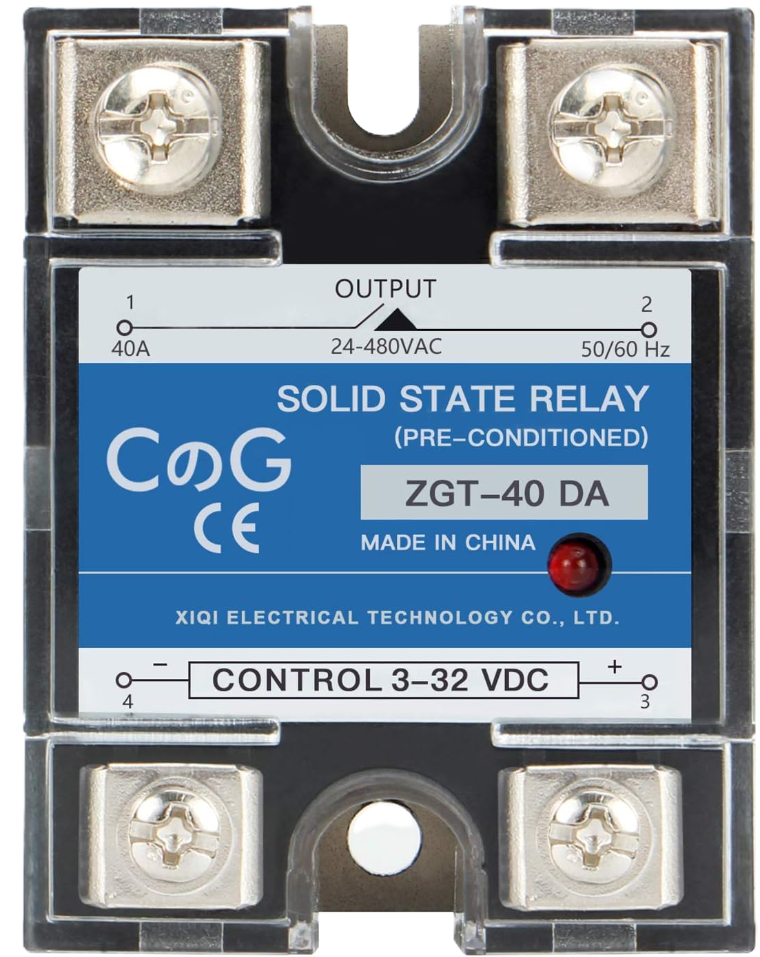 |
CG Solid State Relay SSR-40DA DC to AC Input 3-32VDC to Output 24-480VAC 40A Single Phase Plastic Cover | Amazon |
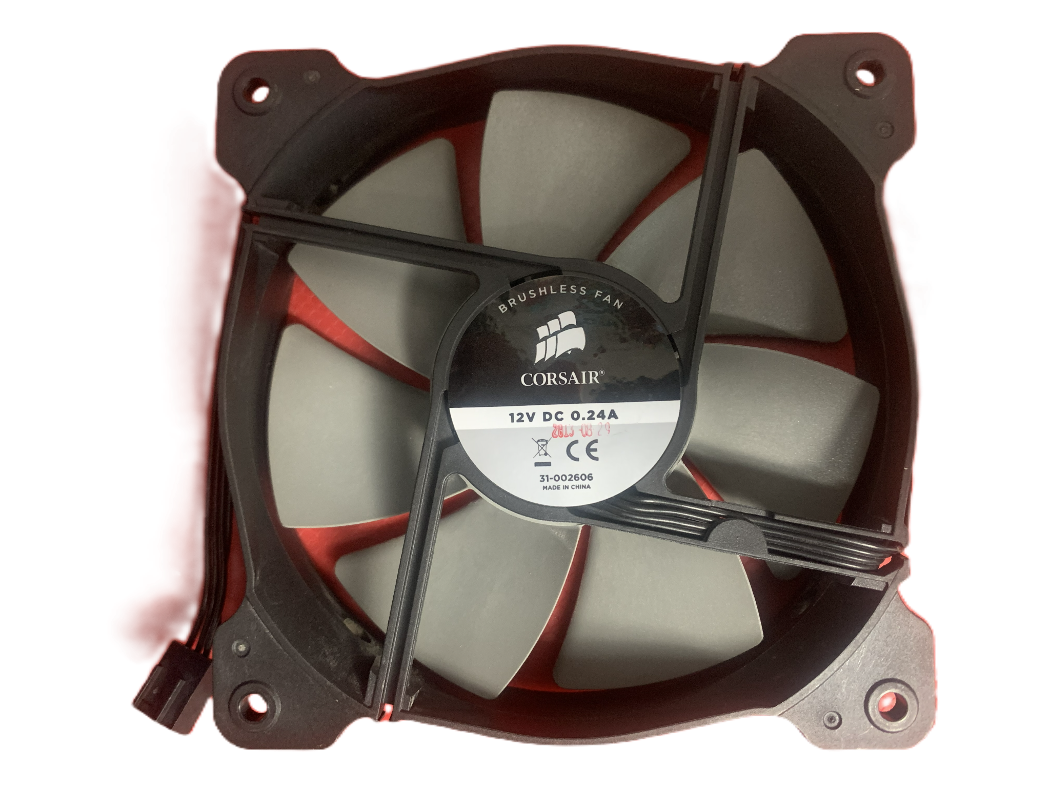 |
12V DC Fan. 4.5" diameter. The speed of this fan can be controlled using a PWM signal. | I recovered mine from an old CPU cooler. |
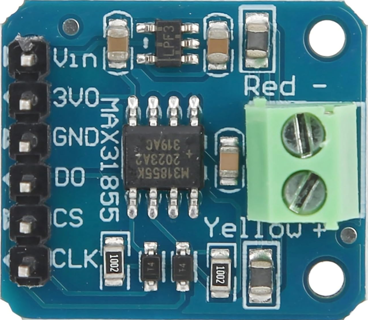 |
4Pcs K Type Thermocouple Temperature Sensor Module MAX31855 SPI Port Thermocouple Board 3 to 5V DC. You only need 1 module but it never hurts to have spares. The ones I purchased came in a pack of 4. |
Amazon |
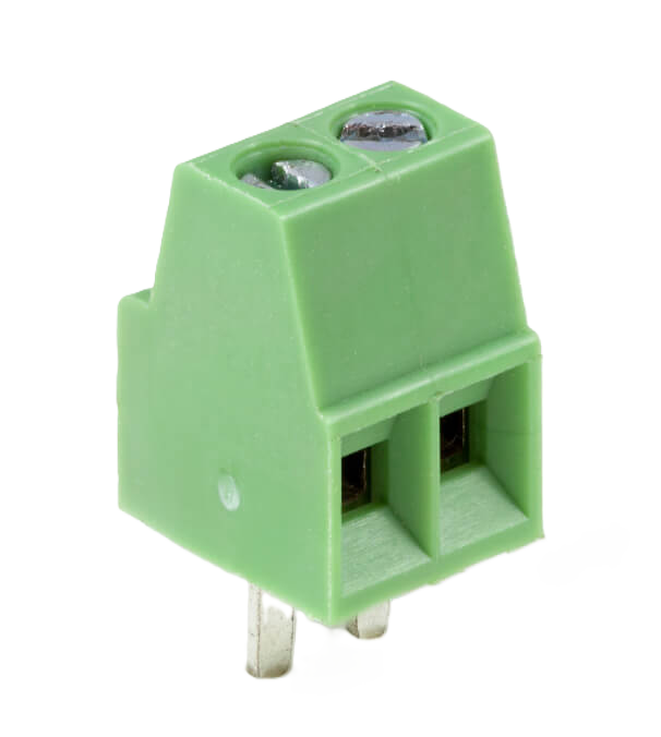 |
2 Pin PCB mount screw terminal | |
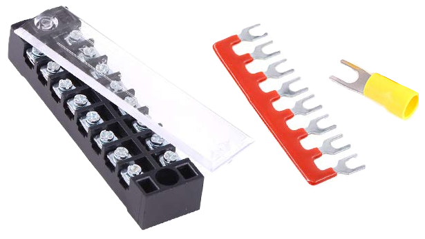 |
Glarks 70Pcs(5Sets) Terminal Block Set, 5Pcs 8 Positions 600V 15A Dual Row Screw Terminals Strip + 5Pcs Pre-Insulated Barrier Strips + 60Pcs Insulated Fork Wire Connector (8P+Fork Connector). | Amazon |
| 12V DC Power Supply | 12V 1A DC power supply | Scrounged from other electronics |
4 x 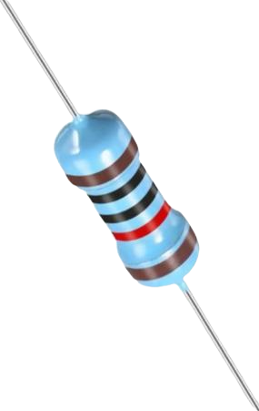 |
10k resistors | |
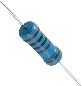 |
1k resistor | |
3 x 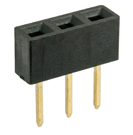 |
3 Pin female headers. These are used as sockets for the buck converters and the DMP3099L breakout board. | |
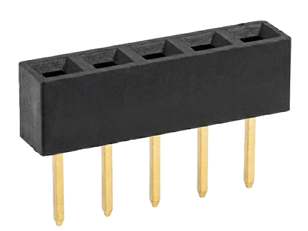 |
5 Pin female header. This is the socket for the rotary encoder cable. | |
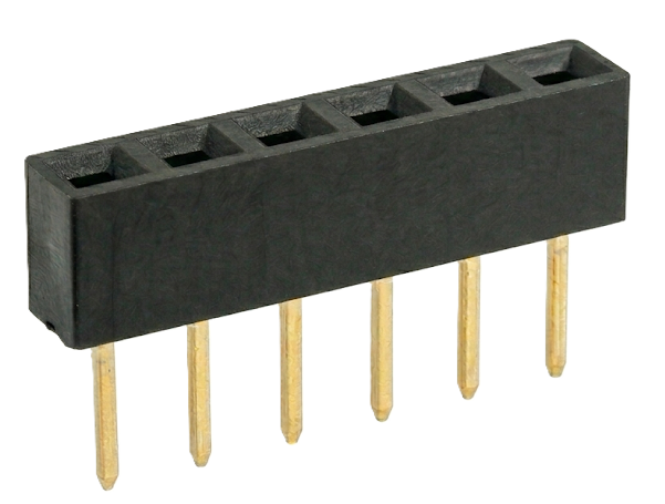 |
6 Pin female header. This is the socket for the MAX31855 module. | |
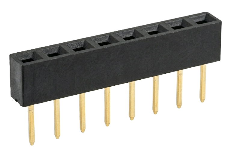 |
8 Pin female header. This is the socket for the TFT display cable. Only 8 pins of the TFT display are needed. | |
2 x 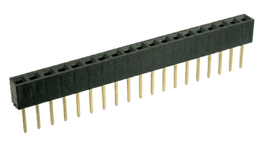 |
19 Pin female headers. These are used to form the socket for the EPS32 module. | |
 |
2 Pin male header. This is the attachment point for the SSR control cable. | |
 |
4 Pin male header. This is the attachment point for the fan control cable. | |
| Wire | 22AWG solid core wire: used to make connections on the breadboard. 26AWG (soft) wire: used to make a variety of "signal" cables (such as the one from the rotary encoder on the front panel to the perfboard). If you don't like making up your own cables, you might get away with using prebuilt wires with dupont connectors on either end. I like the flexibility of the soft silicone coated wire. |
|
| Miscellaneous | You'll need a variety of dupont connectors if you want to make up the same cables as I did (usually come in a kit) and, of course, an appropriate crimper. You'll also need some crimpable wire connectors and an appropriate crimper if you want to use the Terminal Strip to make your connections. |
Circuit Design
Here is a schematic of the replacement circuit for the "intelligent" guts of the hotplate and a brief description of
the various parts of the circuit.
Power Regulation
The 12V power supply feeds into the 5V buck converter. The output of the 5V buck converter feeds into a 3.3V version of the buck converter. These converters are very nice. They have the same footprint as a TO220 78xx regulator but are much more efficient, making them easy to use (no heat sinks are required for this project).
Sockets
The Rotary Encoder, Thermocouple and TFT Display boxes on the schematic represent the perfboard sockets where these components connect.
Fan Control
This section is the interface to the cooling fan. I discovered during testing that my fan will continue to run even if the PWM signal is 0 - meaning that I could not stop the fan using the PWM signal alone. So Q1 and Q2 allow the MCU to shut off power to the fan entirely when it should not be running. Q4 and the associated resistors are used to level shift the fan speed control (FAN_PWM) from the 3.3V of the ESP32 GPIO to 5V required by the fan.
SSR Control
This section is the interface to the SSR that operates the heating element of the hotplate. As with the FAN_PWM signal, this part of the circuit level shifts the SSR_PWM signal from 3.3V to 5V.
Note
It is not a good idea to try to cycle the PWM signal to the SSR rapidly. It is not capable of reacting to a fast signal (such as the one used to control the fan speed). So, in the software, the PWM signal to the SSR is configured to run on a 1Hz cycle (1 cycle per second). As a result, the SSR PWM signal determines the portion of each second that the SSR is turned on. And the lower limit of the PWM signal is long enough for at least 2 cycles of a 50Hz AC signal to occur (in case you are using this in Europe. At 60Hz there will be slightly more than 2 cycles). The PWM signal is allowed to go to 0, to turn the SSR off completely, but when it is on, the lower limit applies.
MCU
This section shows the connections to the ESP32 module.
Breadboarding
I did breadboard the circuit initially to work out the bugs and verify proper operation. Here is a Fritzing drawing that gives another perspective on the circuit and may help you when it comes to wiring it up on perboard. The Fritzing project for this layout is also available in the repository.
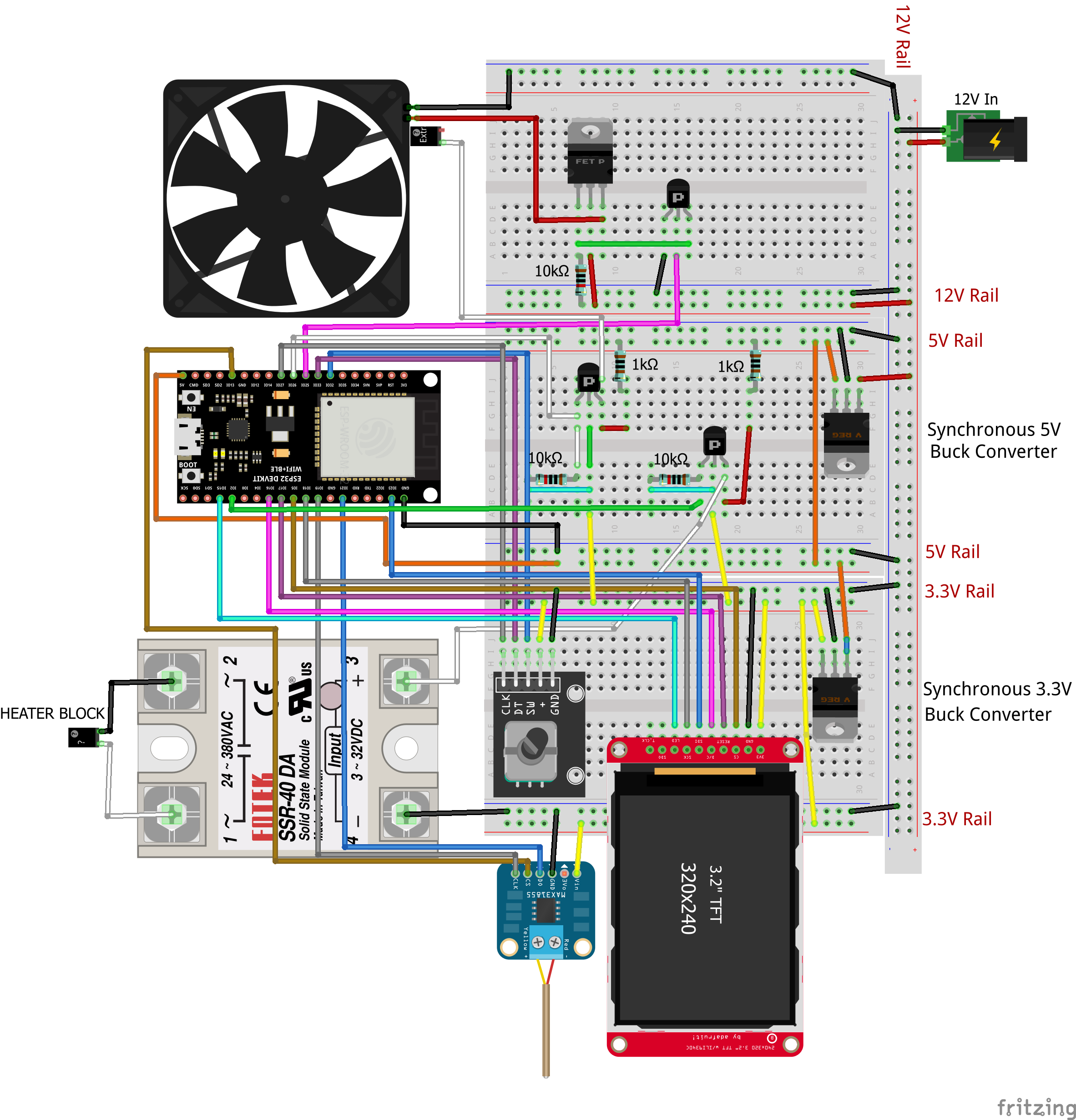
For testing, I wired the SSR output (where the heater block would connect) to a lightbulb socket instead. I could then watch the lightbulb flash at a varying rate to confirm that the circuit was operating correctly. (This was one of the last tests I performed before soldering up the perfboard.)
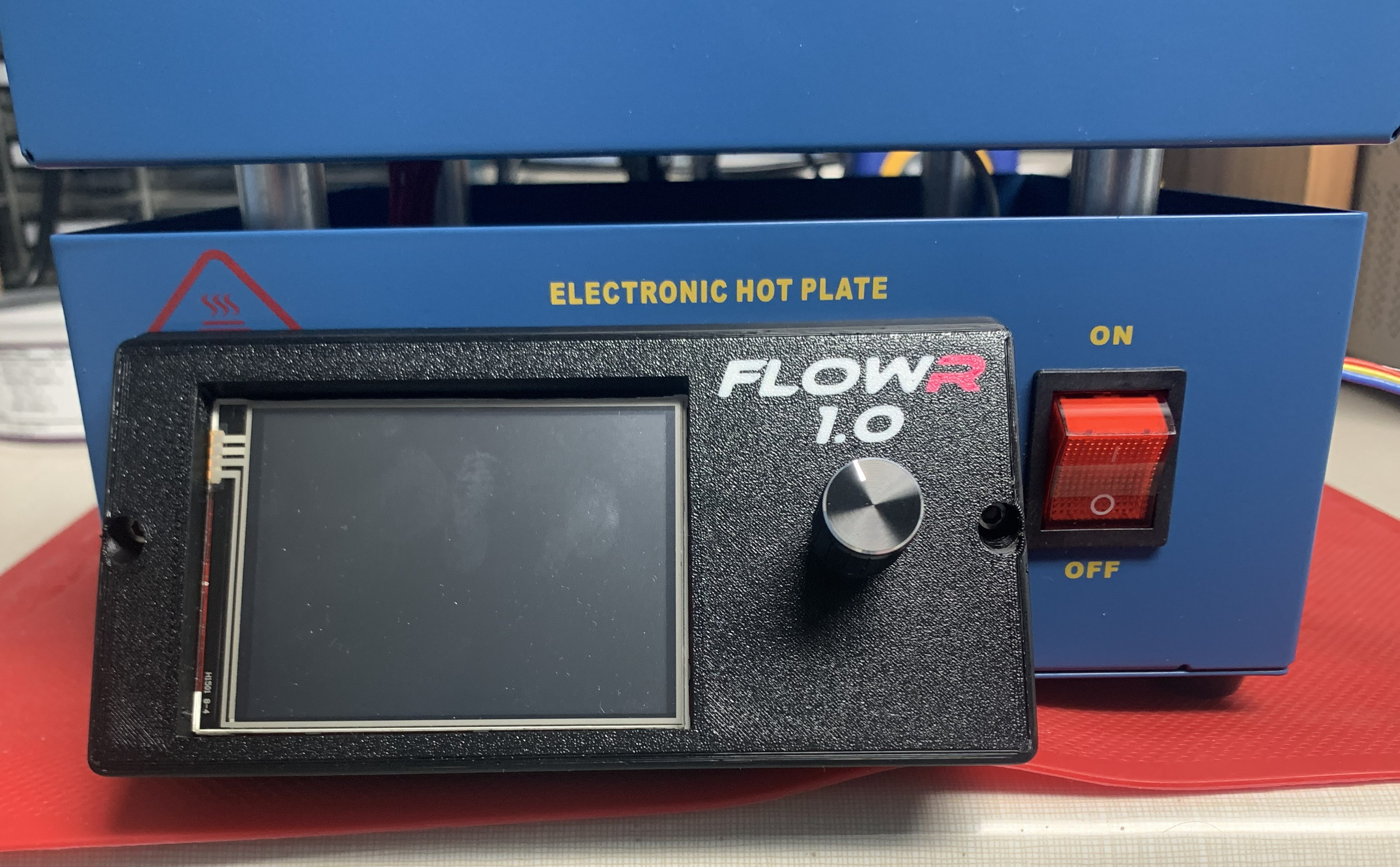
3D Printed Parts
Since I have a 3D printer, I decided to design and print my own front panel as well as a stand for the fan, so that I could position it above the surface of the hotplate. And just for fun and to make it look a little more professional, I decided to put a name on the front panel: FLOWR 1.0.
A picture of my fan stand can be seen at the top of the Overview page.
I also designed some supports for the perfboard to hold it in place. I discovered that, even with my front panel, there was not sufficient space to easily plug in the display and rotary encoder cables, so the perfboard supports also serve to position the board far enough back from the front side of the hotplate enclosure to not interfere with the cable connectors. Lastly, I decided to print my own strain relief for the fan cable which runs from inside the hotplate and connects to the fan on the outside.
All of these parts can be found on Prusa's Printables web site:
Front Panel, etc..
Fan Stand.
In the repository (and on Printables), you will also find a template (Front Panel Drill Template.pdf) for drilling the front of the hotplate to install the front panel (and perfboard supports).
Construction
Construction of the hotplate begins with its deconstruction. I tried to retain as much of the existing wiring as possible in order to limit the amount of rework.
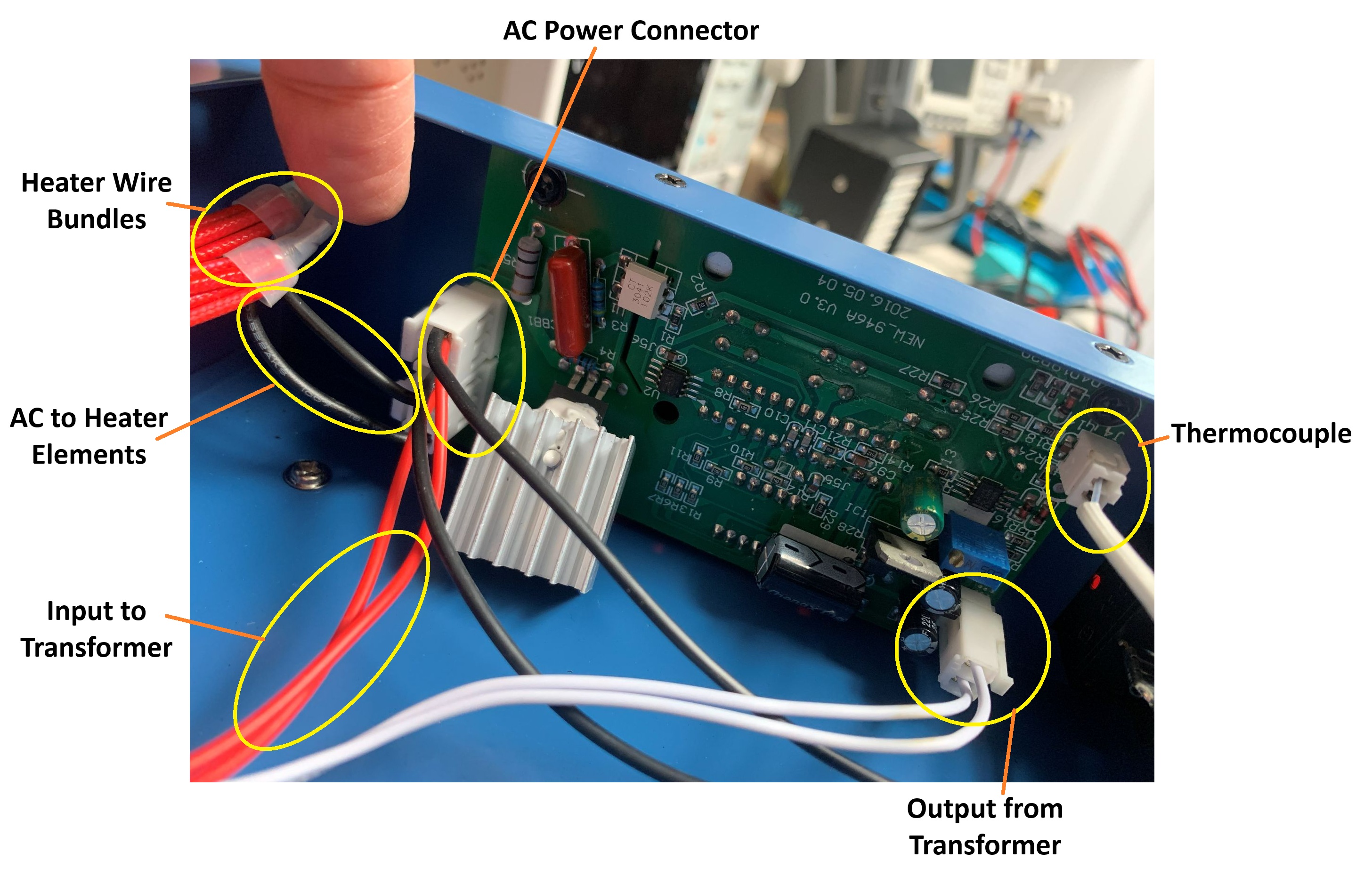
Disassembly
These images show the original internals of the hotplate once the bottom plate is removed:
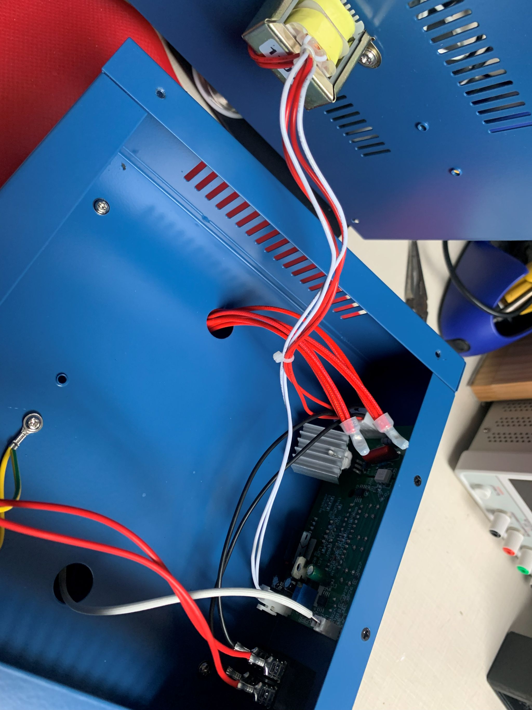
- Disconnect all connectors from the PCB
- Remove the PCB, held in by 2 screws, which includes the buttons and LED display
- Release all wires from the AC Power Connector. Try to keep all of the black wires as long as possible by releasing the pins from the connector before cutting them since these will be reused.
- Remove the step down transformer that is screwed to the bottom plate. It is not required for the build.
Rebuild
Control Circuit
Build the control circuit according to the schematic. Here are some photos of my perfboard. Note that I accidentally used a 6 pin header on the front of the board for the rotary encoder cable when only 5 pins were needed.
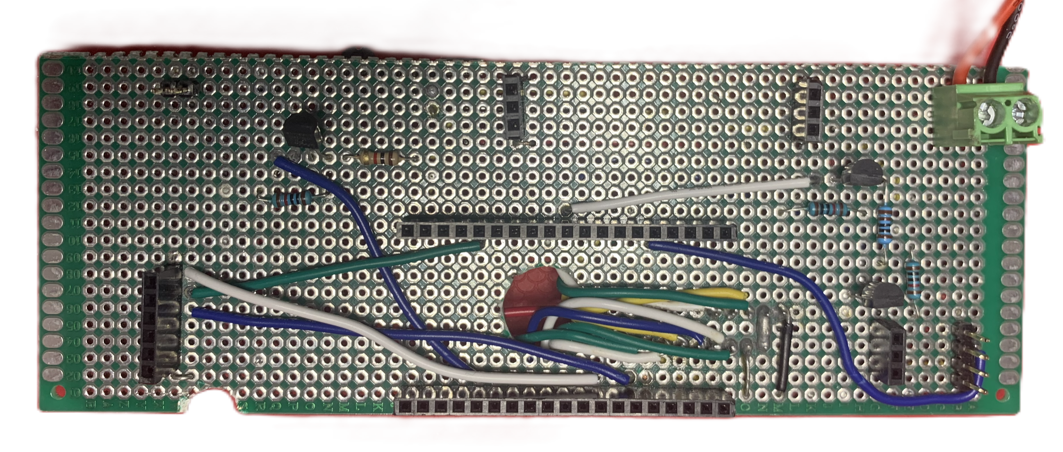
Front of Perfboard (Modules Not Installed)
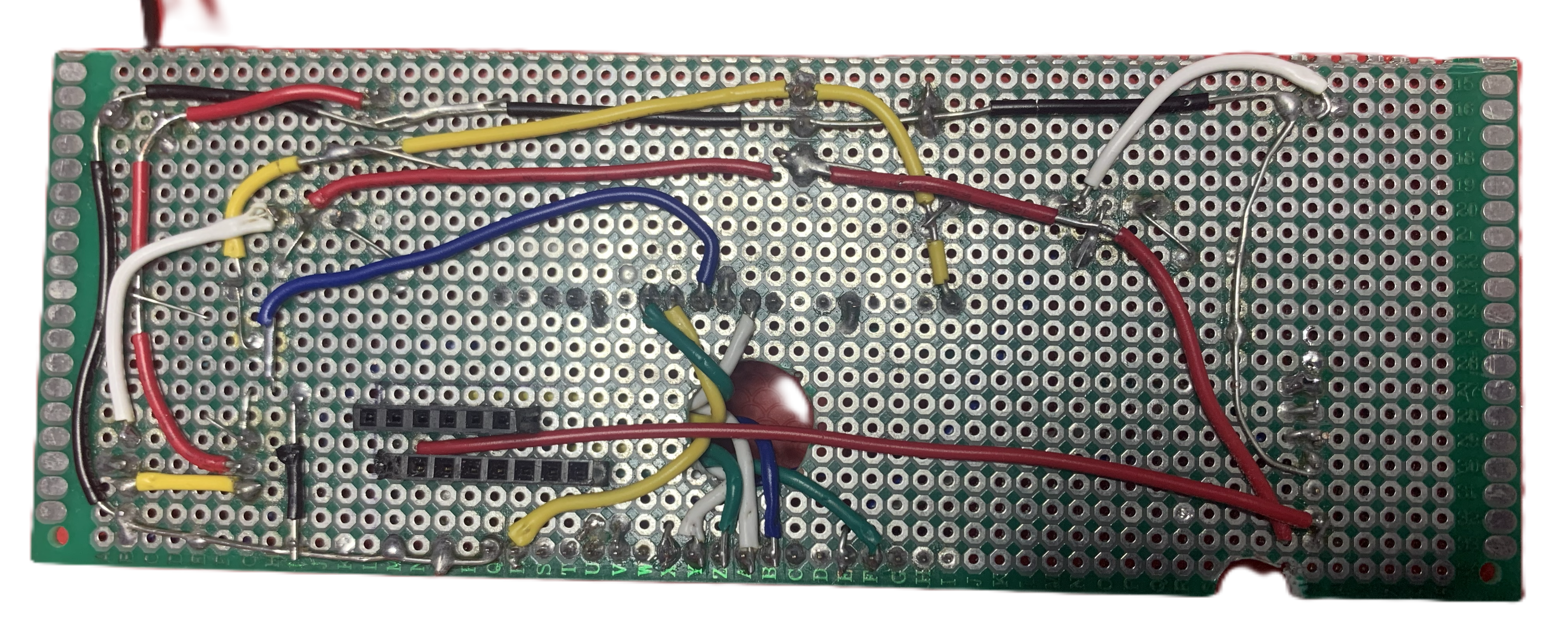
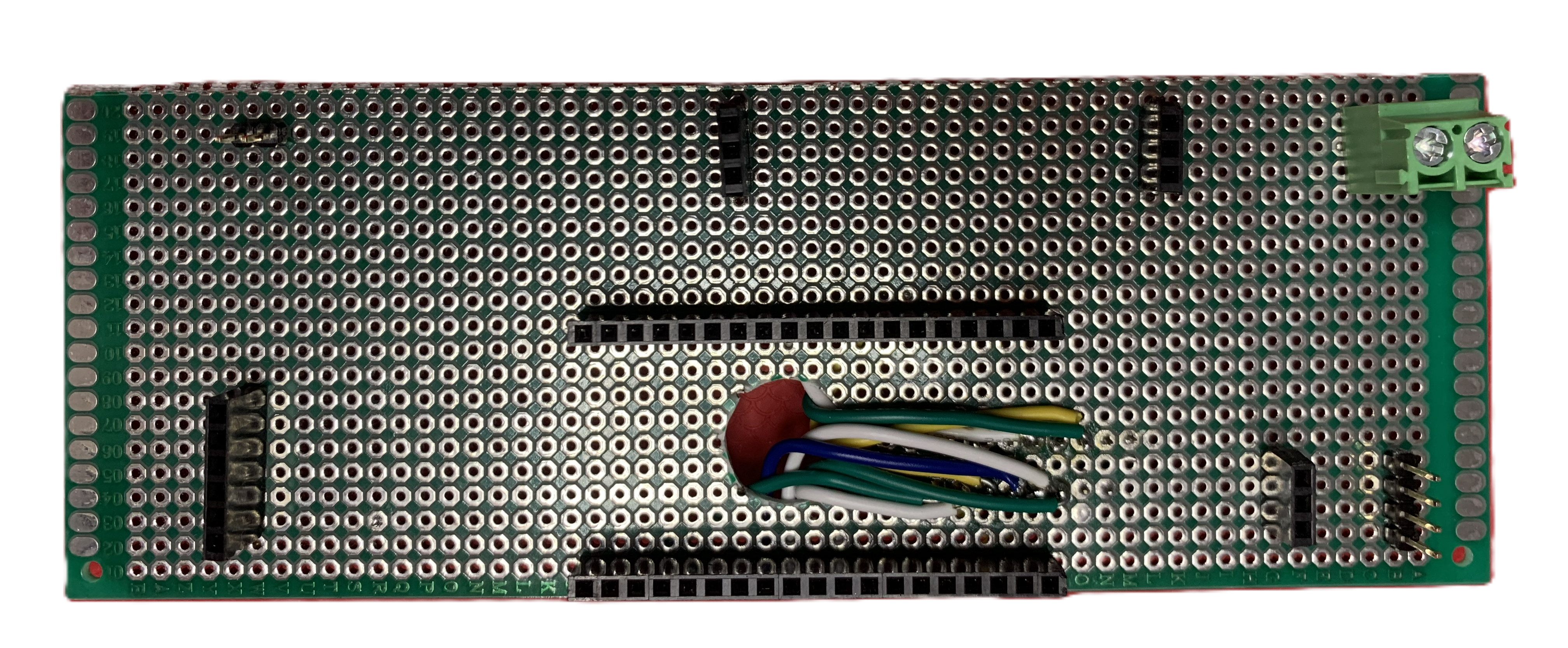
Back of Perfboard (Modules Not Installed)
The notch at the bottom was because I discovered during assembly that a screw interfered with installation of the board.
Note
A little confusing, but the "bottom" in these pictures is actually the top when the hotplate is in use. Most of the photos are from the perspective of when you are working on the wiring, in which case the hotplate will be upside down on your workbench.
Modules
Here is the perfboard with all of the modules and some of the cables installed:
Back of Perfboard (With Modules)
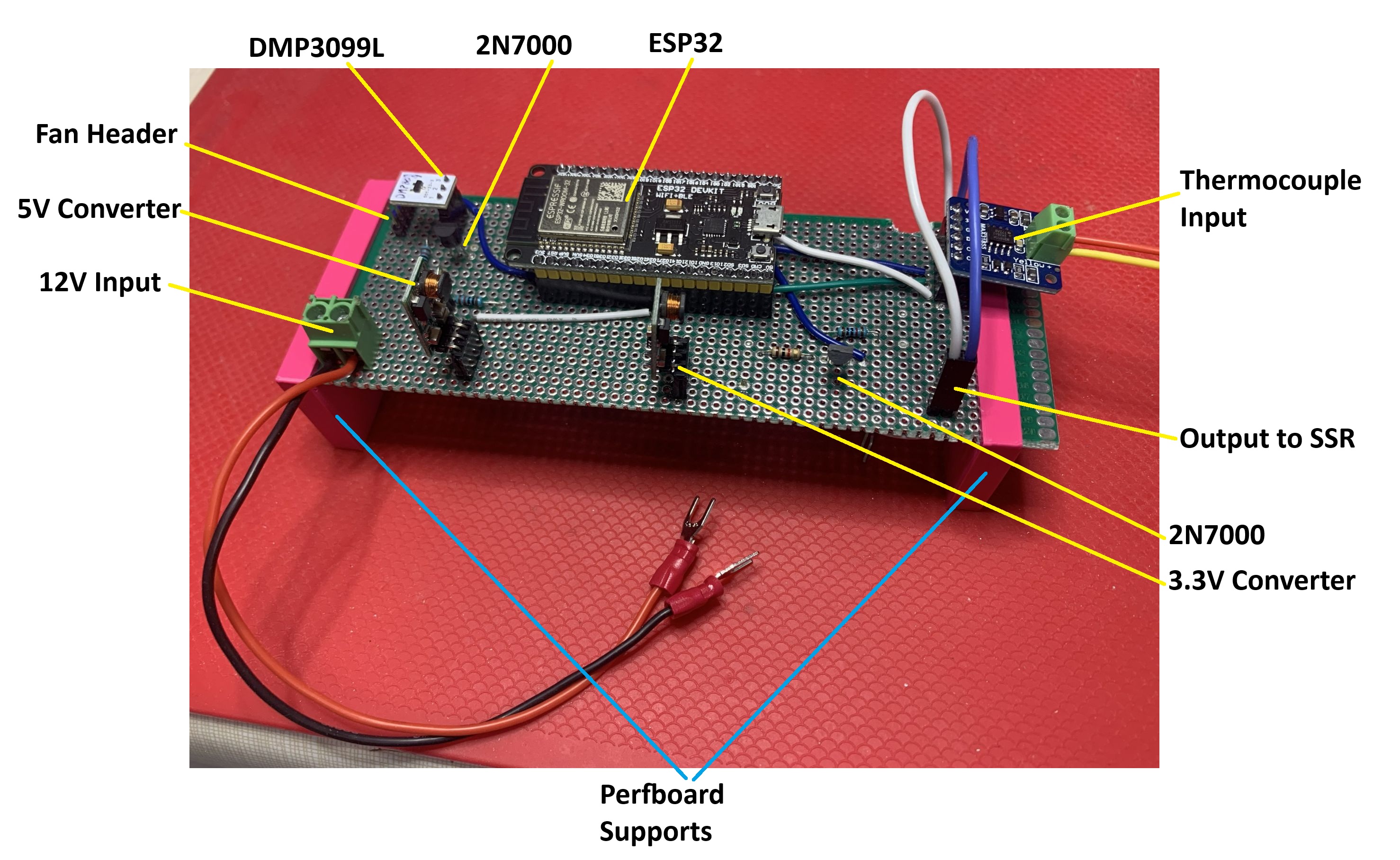
A few things you can't see in the above photo:
- I constructed a 4 wire fan cable that would attach to the Fan Header (the header can just be seen below the DMP3099L). This cable was not installed when I took the photo. The 4th wire is for reading the actual speed of the fan. It's not used but I decided to include it in case I wanted that reading in the future.
- The cable attached to the Output to SSR ends in fork terminal connectors (like the 12V Input cable).
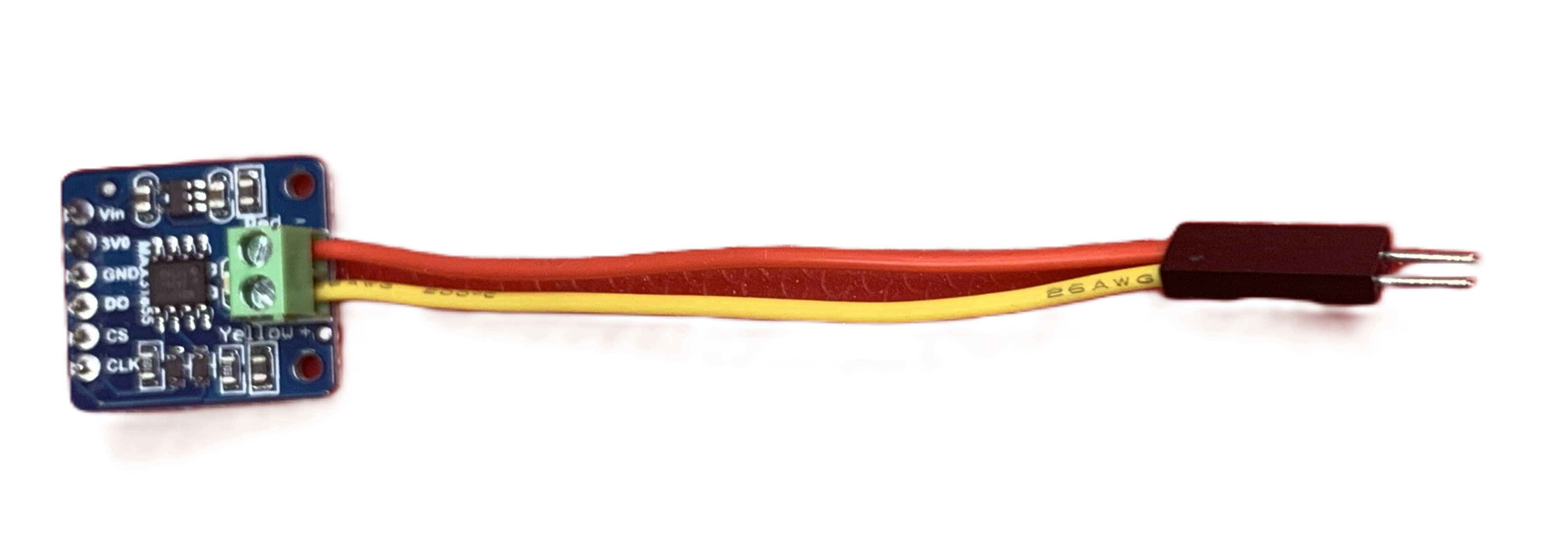 The existing thermocouple cable was too short to reach the MAX31855 module, so I constructed an extension
cable with a dupont connector (which can also be seen in the above image of assembled perfboard).
The existing thermocouple cable was too short to reach the MAX31855 module, so I constructed an extension
cable with a dupont connector (which can also be seen in the above image of assembled perfboard).
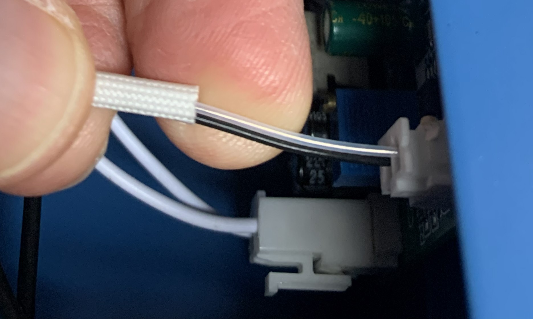 Since the colours of the existing thermocouple wires did not follow any standard I could discover, I
found some information indicating that the negative wire of a K-type thermocouple is magnetic while
the positive wire is not. Based on this, I found that the clear coated wire is the negative
wire and the black one is the positive. Make sure to connect the wires correctly to the MAX31855.
Since the colours of the existing thermocouple wires did not follow any standard I could discover, I
found some information indicating that the negative wire of a K-type thermocouple is magnetic while
the positive wire is not. Based on this, I found that the clear coated wire is the negative
wire and the black one is the positive. Make sure to connect the wires correctly to the MAX31855.
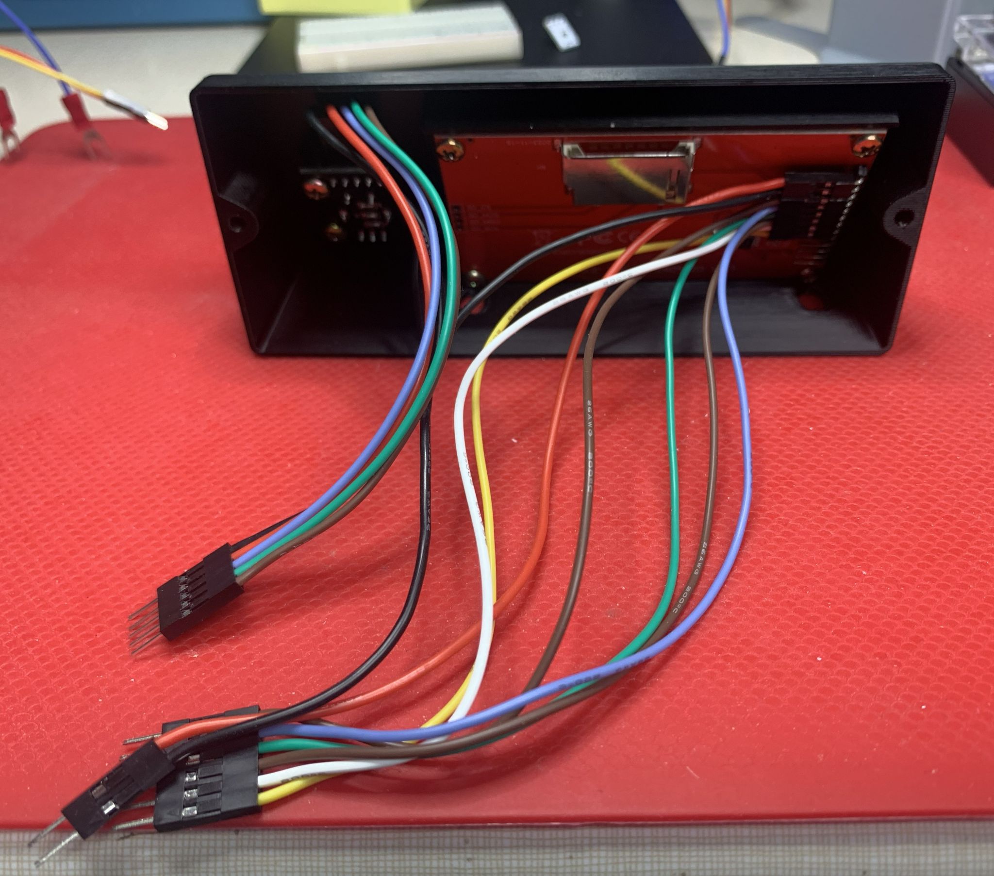
Front Panel
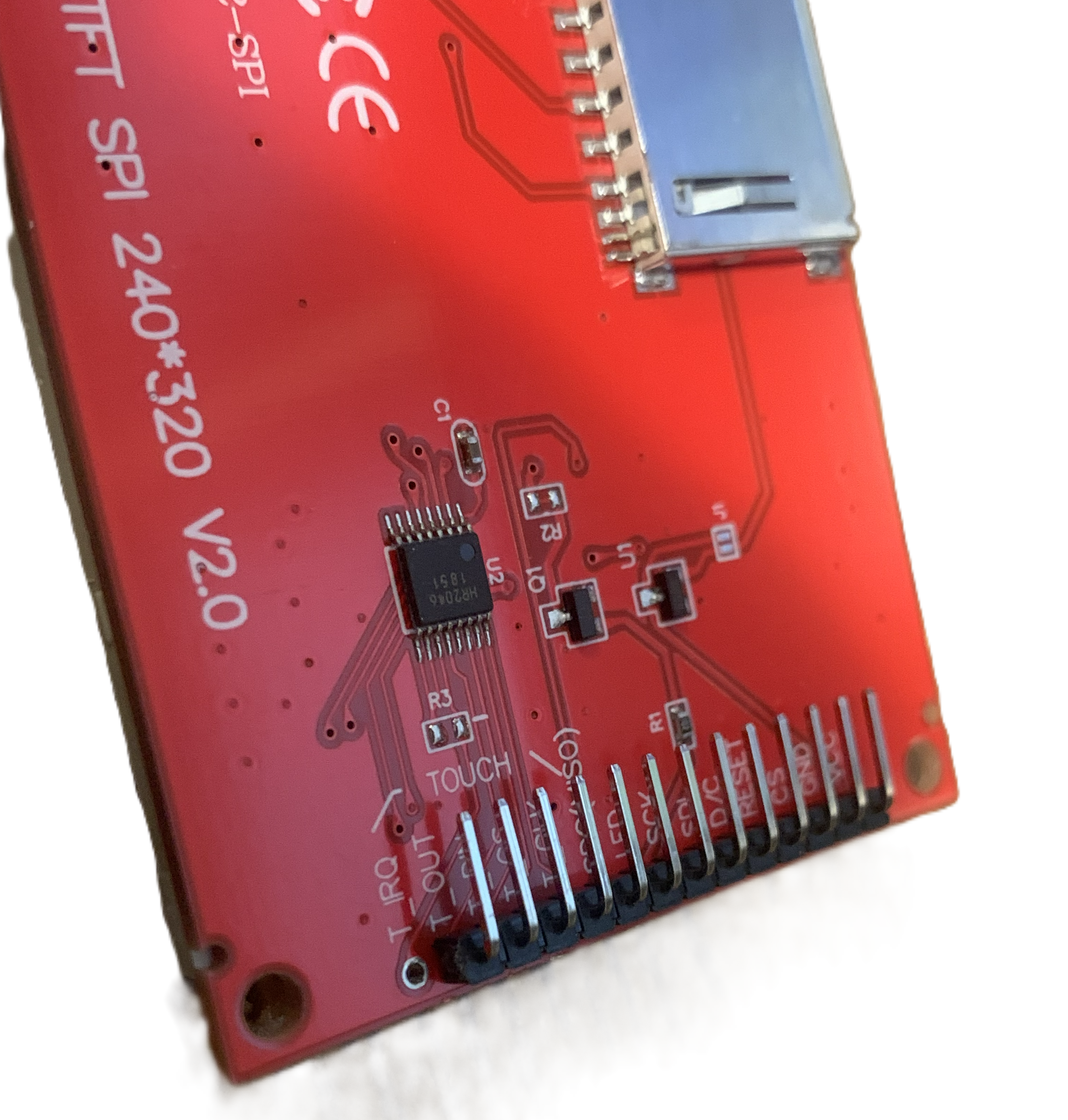 I replaced the TFT screen header with a 90 degree header, shown here, so that the cable could be
connected without sticking out too far.
I replaced the TFT screen header with a 90 degree header, shown here, so that the cable could be
connected without sticking out too far.
Front panel with rotary encoder, tft screen and cables installed.
Assembly
The following is a list of the steps I took in no particular order:
- Crimp fork wire connectors to the end of each of the black wires left behind from the original hotplate wiring (there should be 4 of them).
- Optional: Add heatshrink tubing around both ends of the hot and neutral wires running from the electrical cord inlet at the back to the power switch on the front panel (two red wires).
- Create a wire to ground the bottom plate (this is the blue wire in the photos). I used ring crimp connectors on this wire. Scrape off some paint on the bottom plate near an existing screw hole to attach one end of this wire.
- Cut the wire from the 12V adapter, leaving it long enough to reach the terminal strip. Crimp fork wire connectors to the end of the two wires and note which one is the positive voltage. Make sure you connect power to the perfboard in the correct polarity. There is no reverse polarity protection.
- Attach the 12V adapter at the back of the enclosure (I used a 3M velcro picture hanging strip).
- Attach the terminal strip to the enclosure (I drilled pilot holes and screwed it in place).
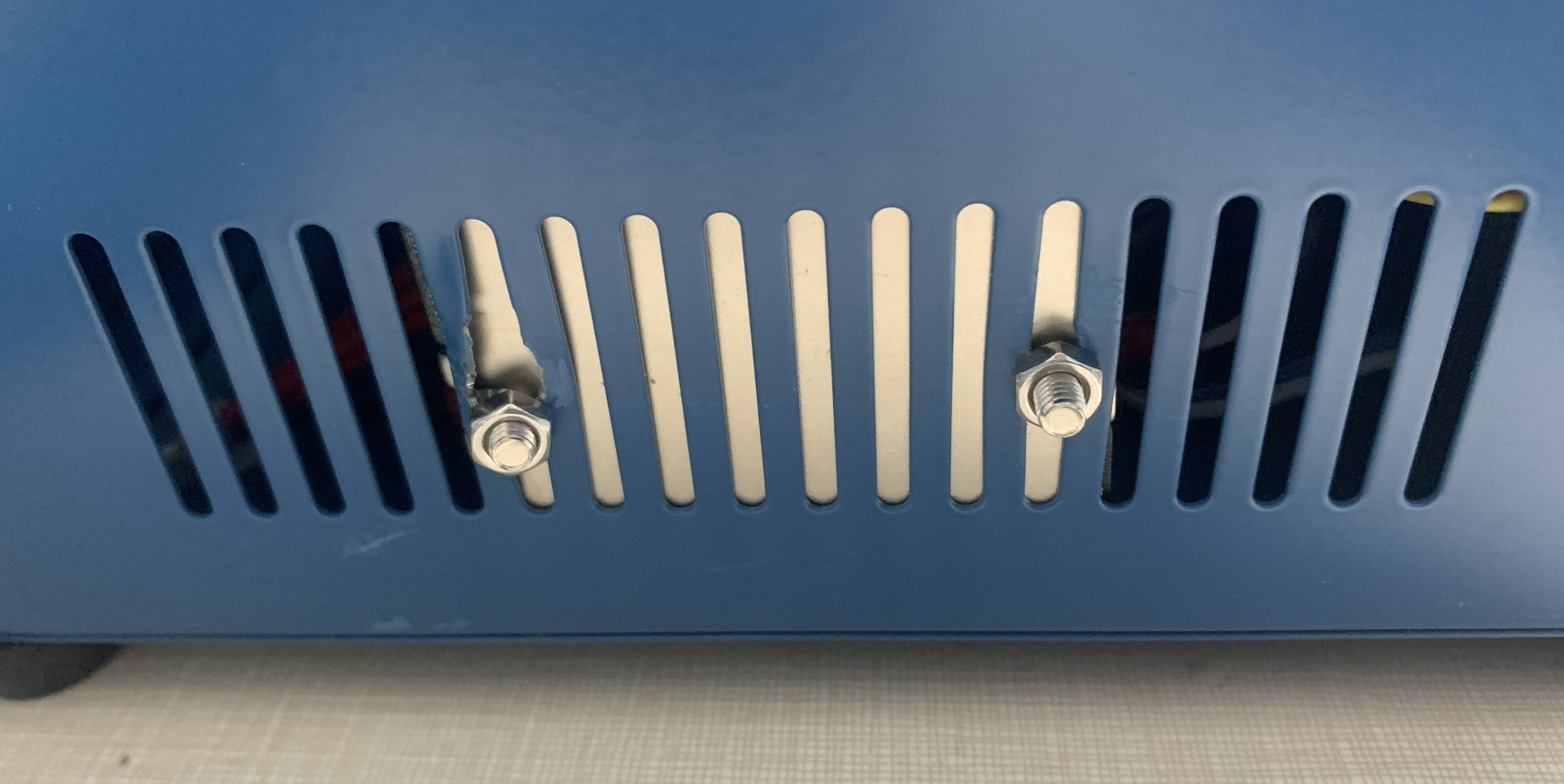
- Attach the SSR. Since mine had a heat sink on the back, I attached it at one of the side grills so it would have air cooling.
- Drill a hole for the fan cable.
You have to attach the (3D printed) front panel, perfboard and perboard supports together using bolts through the front panel of the hotplate enclosure. It's a little tricky because it's hard to see when you have the proper alignment and the perfboard (as I made it) is a tight fit.
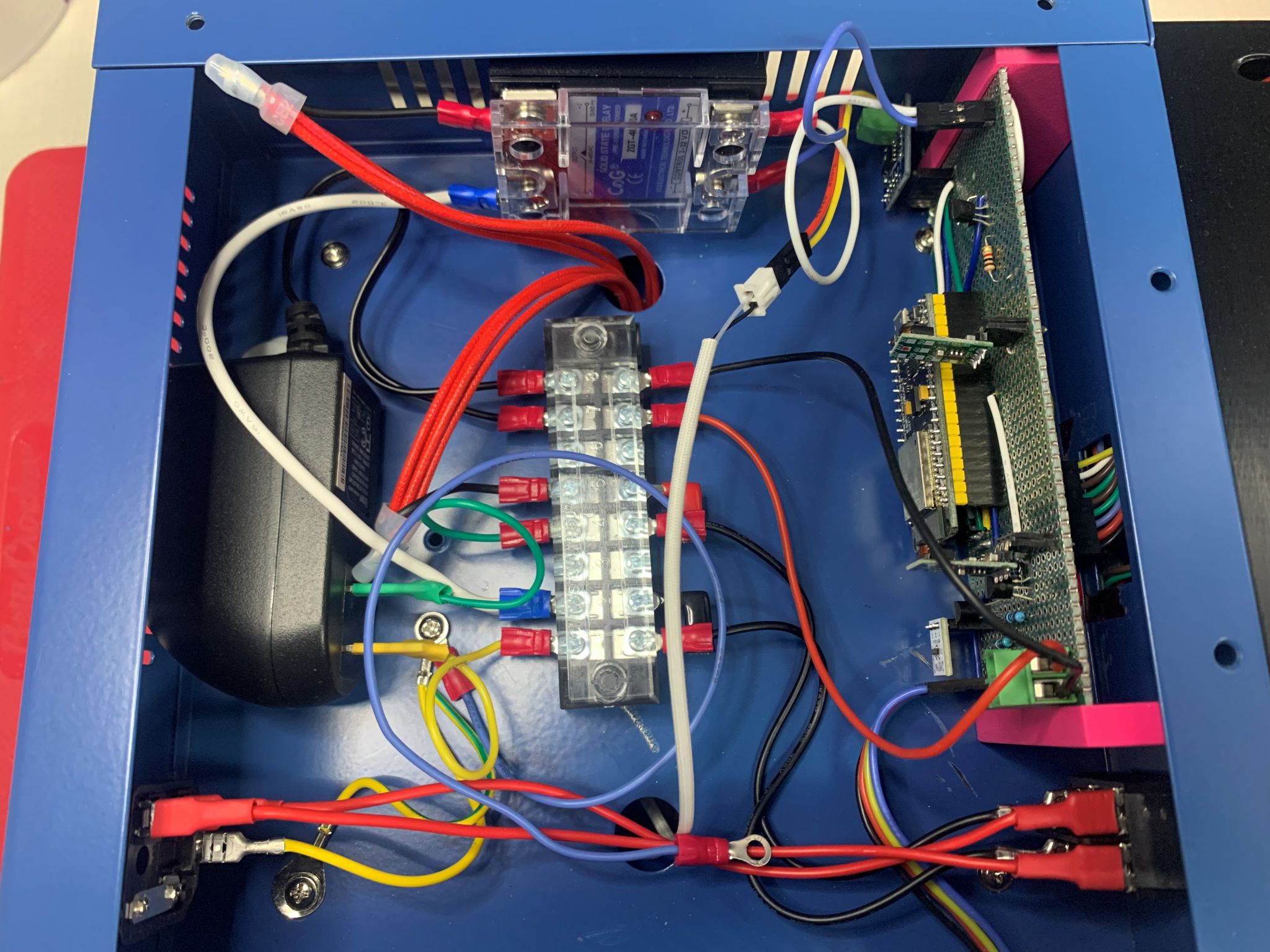
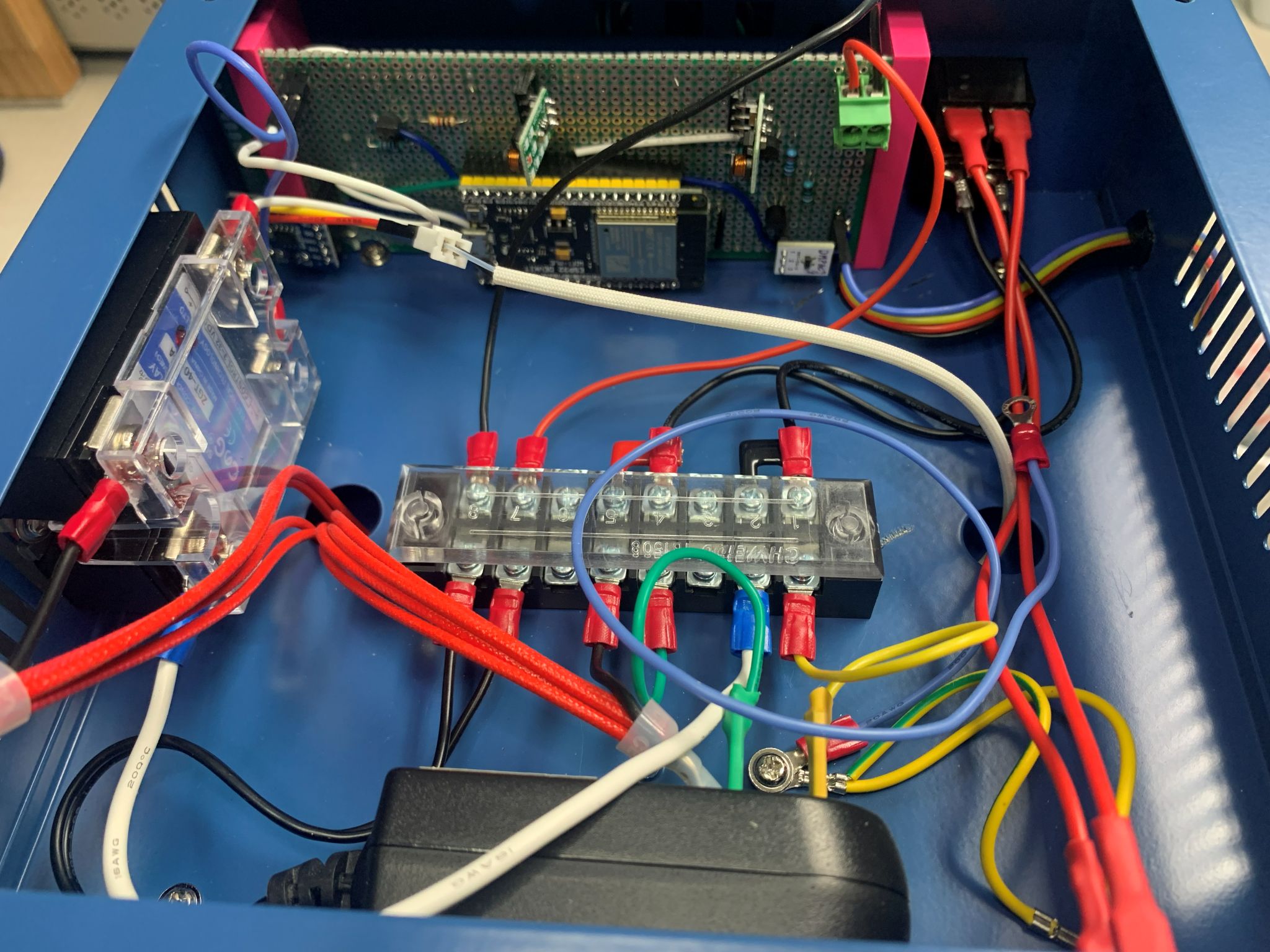
The following photos should allow you to work out the final connections once everything is in place.
Views of the assembled hotplate
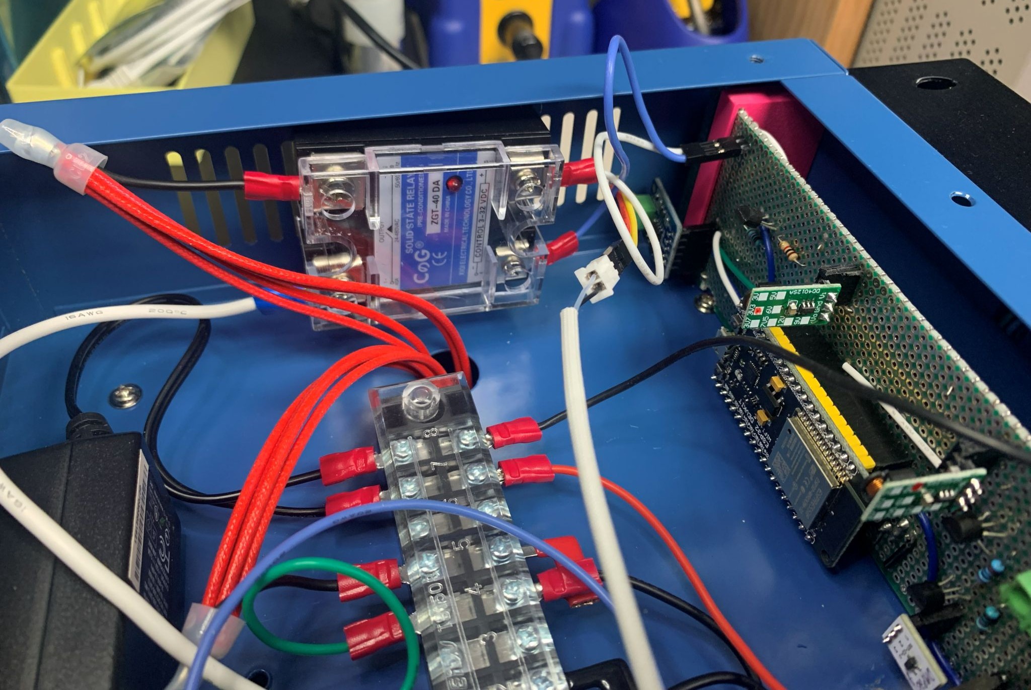
Outside view of SSR