User Guide
Controls
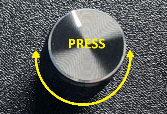 The hotplate is operated using a single rotary encoder. The features of the
application are controlled by a combination of rotating the knob and pressing
the button built into the encoder shaft. Since the encoder can be rotated
slowly or quickly and the button can be held pressed for a short or "long" time,
this single control allows for 4 different interactions.
The hotplate is operated using a single rotary encoder. The features of the
application are controlled by a combination of rotating the knob and pressing
the button built into the encoder shaft. Since the encoder can be rotated
slowly or quickly and the button can be held pressed for a short or "long" time,
this single control allows for 4 different interactions.
When modifying settings, speed of rotation usually affects the amount by which the setting increases or decreases for each "click". (Some settings have such a small range of value that speed of rotation is not relevant.)
There are a few cases where different operations are performed based on whether the button was short or long pressed and these will be pointed out below. A long press is registered if you hold the button down for anything longer than about 1 second.
General Rules of Operation
In general, the application works as follows:
- Rotate the knob clockwise or counterclockwise to cycle through the on screen elements that are "actionable" (meaning they can be modified or activated). The currently selected element will be highlighted.
- Short or long press the button. If the selected screen element represents a button, this starts an operation and/or switches to a new screen. If the selected screen element represents a setting, the element colours will change to reflect that you are now modifying the setting value.
- To modify the selected setting, rotate the knob.
- To finish modifying the setting, press the button. The element will again be displayed with the colours used to indicate that it is "selected" (but no longer editable).
Screens and Features
Welcome
The Welcome screen is shown after power on for about 10 seconds. This screen displays the firmware and configuration version numbers. During this time, the fan will ramp up and down in speed, if it is connected and supports PWM.
Note
If you are using a special build of the software (for debugging purposes) the build type will also be identified on this screen.
Settings
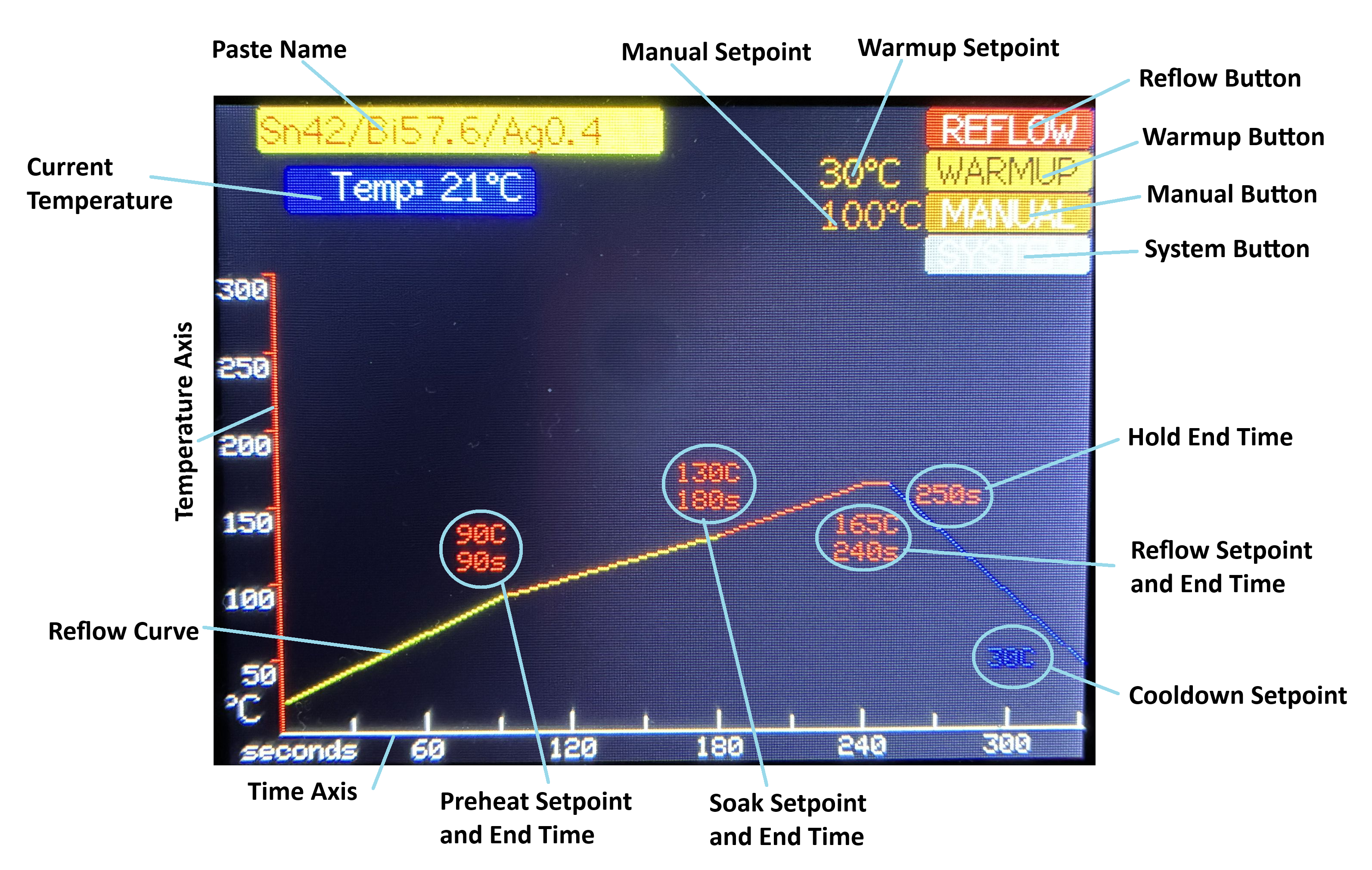
This is the main operating screen of the hotplate. It displays the currently selected solder paste (or "profile") name and a graph of the key points in the configured profile. It also displays the current temperature of the hotplate.
| Screen Element | Description |
|---|---|
| Paste Name | Displays the selected profile (or paste) name. Press to enter a mode where you can cycle through the defined profiles. Rotate the knob to select a profile and then Press a second time to select the displayed profile. Long Press to begin modifying the profile name (takes you to the Solder Paste Name screen) |
| Current Temperature | Displays the current measured temperature of the hotplate. |
| Reflow Button | Press to begin a reflow operation with the currently selected solder paste profile. Takes you to the Reflow screen. |
| Warmup Setpoint | Allows you to modify the temperature setpoint for warmup operations. |
| Warmup Button | Press to begin a warmup operation. Takes you to the Warmup screen. |
| Manual Setpoint | Allows you to modify the initial temperatur setpoint for manual operations. |
| Manual Button | Press to begin manual operation of the hotplate. Takes you to the Manual Control screen. |
| System Button | Press to go to the System screen where system parameters can be modified. |
| Preheat Setpoint and End Time | Allows you to specify the temperature to be reached by the end of the Preheat stage of a reflow operation and the time at which it should be reached (all times are in seconds since the start of the reflow operation). |
| Soak Setpoint and End Time | Allows you to specify the temperature to be reached by the end of the Soak stage of a reflow and the time at which it should be reached. |
| Reflow Setpoint and End Time | Allows you to specify the temperature to be reached by the end of the Reflow stage of a reflow and the time at which it should be reached. |
| Hold End Time | Allows you to specify the time at which the cooldown of the hotplate should begin (until this time, the controller will try to hold the temperature at the Reflow Setpoint). |
| Cooldown Setpoint | Allows you to specify the target temperature to which the hotplate should be cooled before the fan is shut down. Note that you do not set a time at which this temperature should be reached. Instead, the controller will try to cool the hotplate as rapidly as possible while respecting the limit on the rate of cooling that is specified in the system settings. |
| Reflow Curve | Shows the expected progress of the hotplate temperature over time based on the defined reflow temperature and time settings described above. Note that the reflow curve starts at 0 seconds at the currently measured temperature of the hotplate. So it reflects how the temperature would progress if a reflow operation were started immediately, even if the hotplate is currently above room temperature. The reflow curve also reflects the limit on the allowed rate of cooling. Because of this, the temperature reached by the curve (at the right side of the graph) may not be the desired cooldown setpoint temperature. |
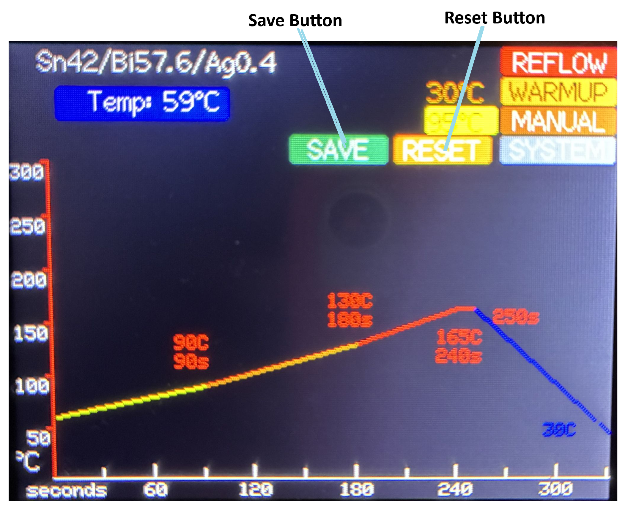
Settings Save and Reset Buttons
If you modify any of the values on the Settings screen, two additional buttons will appear: the Save and Reset buttons.
| Screen Element | Description |
|---|---|
| Save Button | Long Press to save the settings (they are stored in the EEPROM of the ESP32). |
| Reset Button | Long Press to restore all settings to the last saved values (changes are discarded). |
Note
You must Long Press these buttons since their actions are not reversible. A regular Press is ignored.
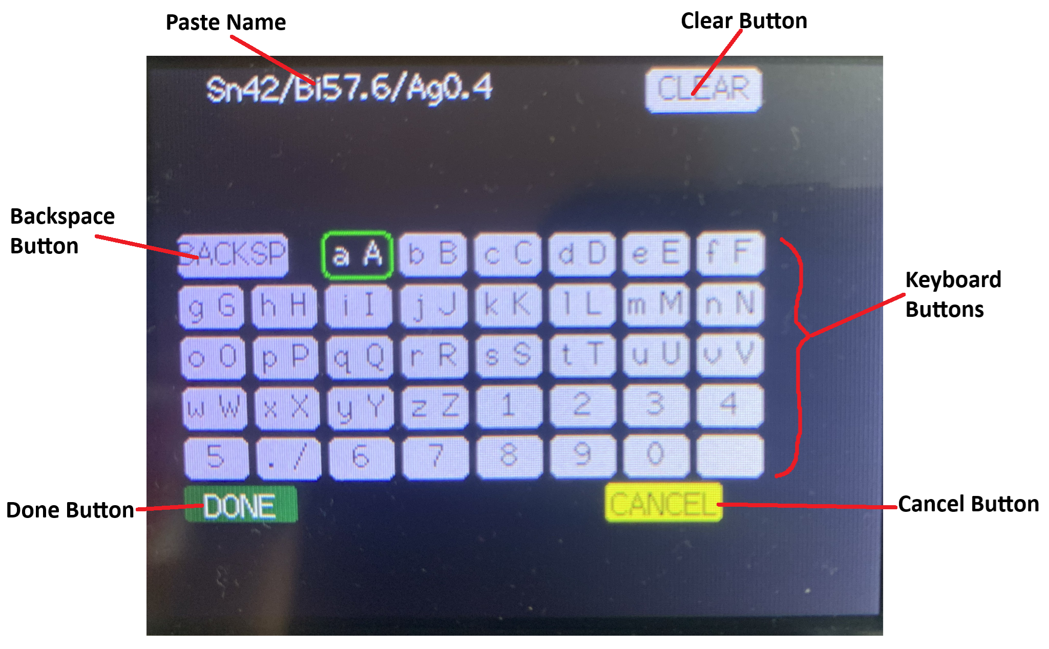
Solder Paste Name
This screen allows you to modify the name of the currently selected solder paste. It is reached by Long Pressing when the solder paste name field is selected on the Settings screen.
| Screen Element | Description |
|---|---|
| Paste Name | Displays the paste name as it is modified. |
| Clear Button | Press to reset the paste name to an empty string. |
| Backspace Button | Press to erase the last character in the paste name. |
| Keyboard Buttons | Press to add the first character displayed on the key to the paste name. Long Press to add the second character (if any) to the paste name. If there is no second character, adds the first character. |
| Done Button | Press to accept the modified paste name and return to the Settings screen. |
| Cancel Button | Press to reset the paste name to the value it had on entry to this screen and return to the Settings screen. |
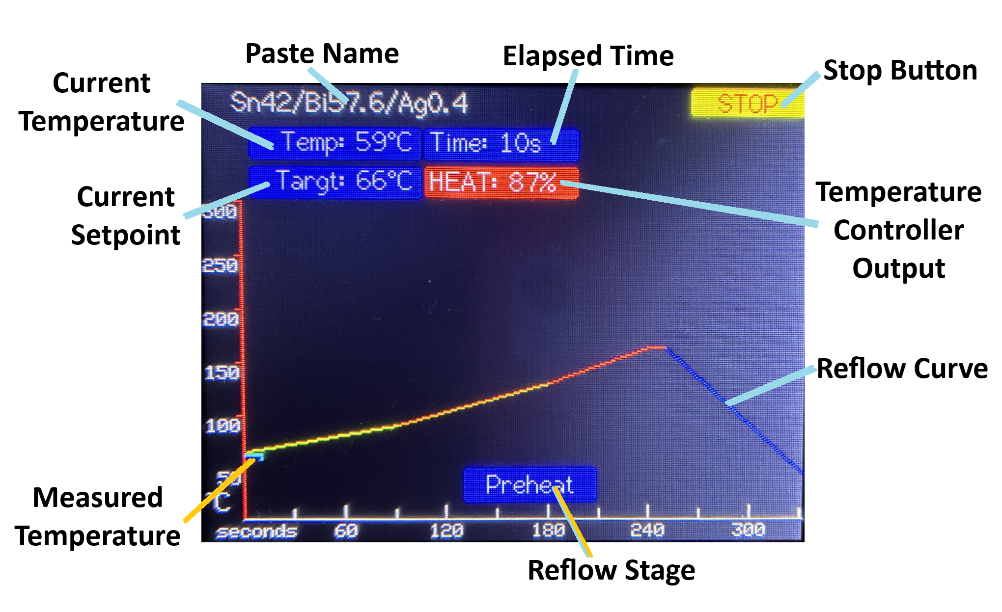
Reflow
This screen is displayed when the hotplate is performing an automatic reflow operation.
| Screen Element | Description |
|---|---|
| Paste Name | Displays the selected profile (or paste) name. |
| Stop Button | Press to cancel the current reflow operation and return to the Settings screen. Note that the heater and fan will both turn off. If you want to use the fan to cool the hotplate, you will need to use the Manual Control operation. |
| Current Temperature | Displays the current measured temperature of the hotplate. |
| Elapsed Time | Displays the elapsed time since the start of the reflow operation. |
| Current Setpoint | Displays the current temperature setpoint. The setpoint will ramp up and down over time so that the hotplate temperature tracks as closely as possible to the reflow curve. |
| Temperature Controller Output | Provides an indication of whether the temperature controller is currently applying heating or cooling to the hotplate. The value indicates the percent of full heating or cooling being called for. The display also switches between a red background, for heating, and blue, for cooling. |
| Reflow Stage | Displays the current stage of the reflow process. |
| Reflow Curve | Shows the expected progress of the hotplate temperature over time based on the defined reflow temperature and time settings for the current profile. |
| Measured Temperature Line | Plots the measured temperature over time. This provides a visual indication of how closely the hotplate temperature is matching the desired profile. If the process takes more than 330 seconds (which is the extent of the graph), the line will wrap back to the left edge of the graph and overwrite the previous values. The markers on the time axis will be updated as they are reached, to reflect the actual elapsed time. |
At the end of the reflow process (once the hotplate has cooled to the specified cooldown temperature), the program will automatically return to the Settings screen.
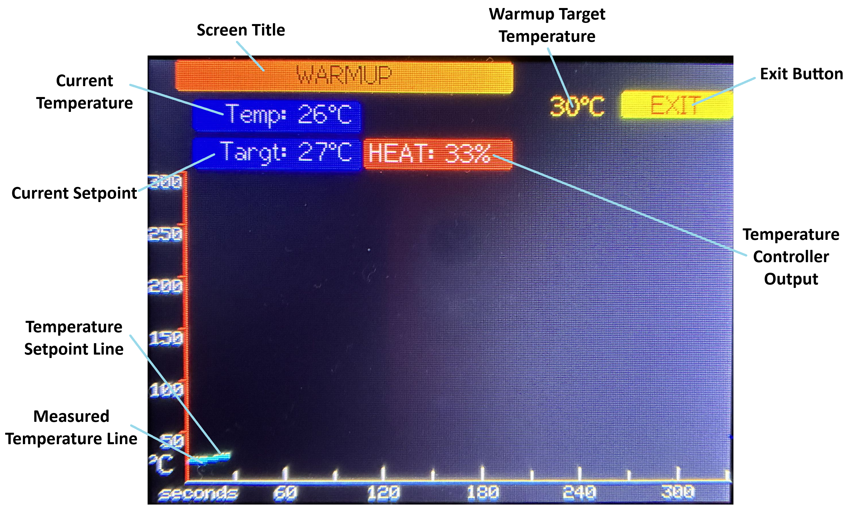
Warmup
This screen is displayed when the hotplate is performing an automatic warming operation. The hotplate will be heated to the preset "warming setpoint" while respecting the configured limits on the rate of warming.
Note
The Warmup operation is only used to heat up the hotplate. It does not support cooling. If you want to cool down the hotplate, use the Manual Control mode.
| Screen Element | Description |
|---|---|
| Screen Title | Indicates that the hotplate is in warmup mode. |
| Exit Button | Press to stop the warmup operation and return to the Settings screen. NOTE that the heater and fan will both turn off. |
| Warmup Target Temperature | Displays the temperature that should be reached and maintained by the warmup operation. This setting can be adjusted on either the Settings or System screens. |
| Current Temperature | Displays the current measured temperature of the hotplate. |
| Current Setpoint | Displays the current temperature setpoint. This setpoint will be automatically ramped up from the initial measured temperature towards the Warmup Target Temperature while respecting the limit on how fast the temperature should be allowed to change (see Max Warmup Rate under the System screen). Automatic ramping of the temperature setpoint (and no support for cooling) is what differentiates the Warmup mode from the Manual Control mode. |
| Temperature Controller Output | Provides an indication of how strongly the temperature controller is currently applying heating to the hotplate. The value indicates the percent of full heating being called for. |
| Temperature Setpoint Line | Plots the temperature setpoint over time. As shown in this screenshot, it is quite possible that the setpoint line will not be easily visible since the measure temperature may be able to closely track the setpoint (if the rampup is slow enough). |
| Measured Temperature Line | Plots the measured temperature over time. This provides a visual indication of how closely the hotplate temperature is matching the desired setpoint. If the warmup operation continues for more than 330 seconds (which is the extent of the graph), both lines will wrap back to the left edge of the graph and overwrite the previous values. The markers on the time axis will be updated as they are reached, to reflect the actual elapsed time. |
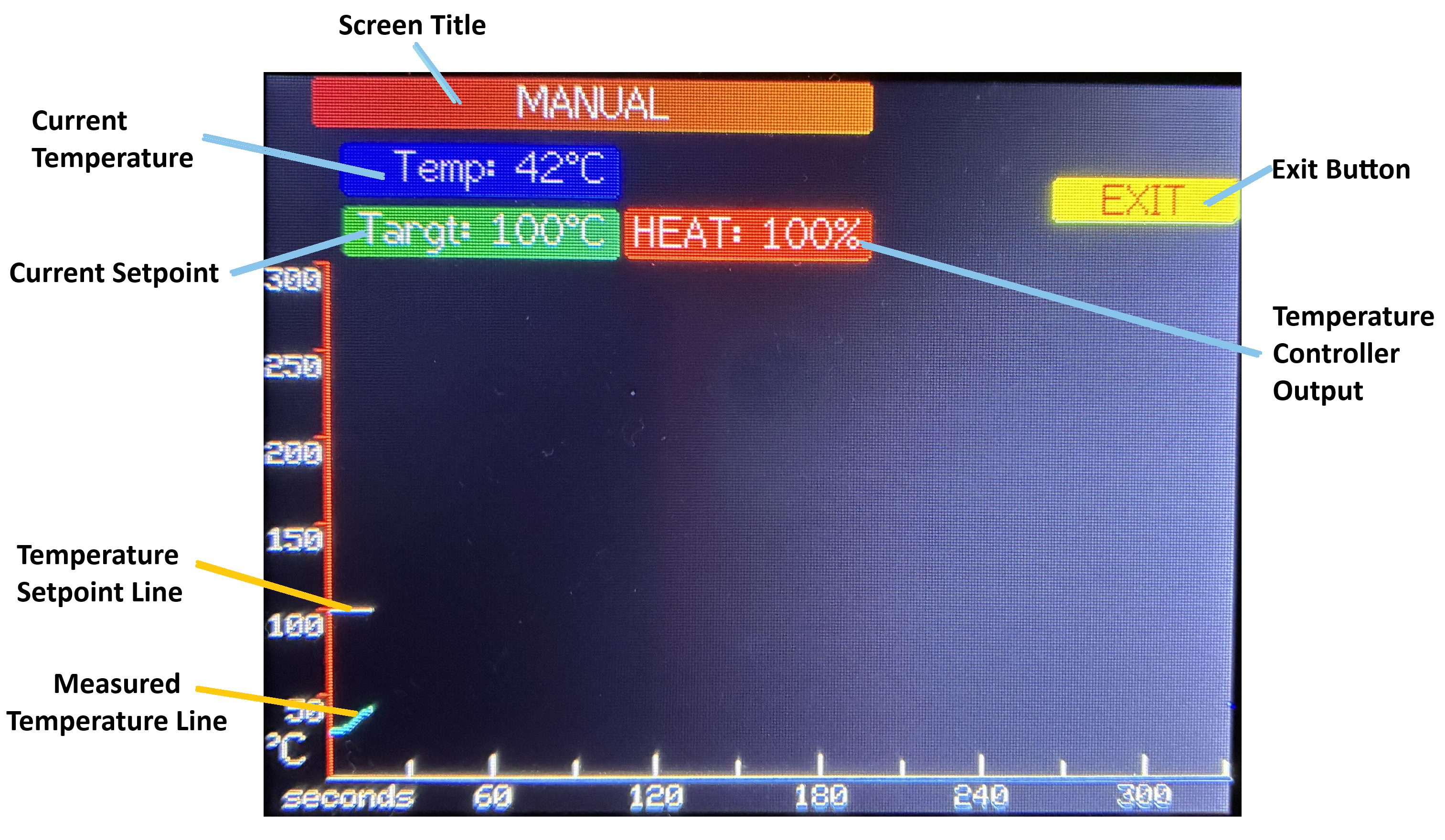
Manual Control
This screen is displayed when the hotplate is being operated manually.
Note
The only setting available during this mode of operation is the temperature setpoint. Because of this, there is no need to select the setpoint to modify it, even though the EXIT button is highlighted as selected.
| Screen Element | Description |
|---|---|
| Screen Title | Indicates that the hotplate is in manual control mode. |
| Exit Button | Press to stop manual control of the hotplate temperature and return to the Settings screen. NOTE that the heater and fan will both turn off. |
| Current Temperature | Displays the current measured temperature of the hotplate. |
| Current Setpoint | Displays the current temperature setpoint. Turning the rotary encoder adjusts this setpoint. Depending on the speed of rotation the setpoint will increase/decrease by 1 degree or 10 degrees. |
| Temperature Controller Output | Provides an indication of whether the temperature controller is currently applying heating or cooling to the hotplate. The value indicates the percent of full heating or cooling being called for. The display also switches between a red background, for heating, and blue, for cooling. |
| Temperature Setpoint Line | Plots the temperature setpoint over time. |
| Measured Temperature Line | Plots the measured temperature over time. This provides a visual indication of how closely the hotplate temperature is matching the desired setpoint. If manual control is maintained for more than 330 seconds (which is the extent of the graph), both lines will wrap back to the left edge of the graph and overwrite the previous values. The markers on the time axis will be updated as they are reached, to reflect the actual elapsed time. |
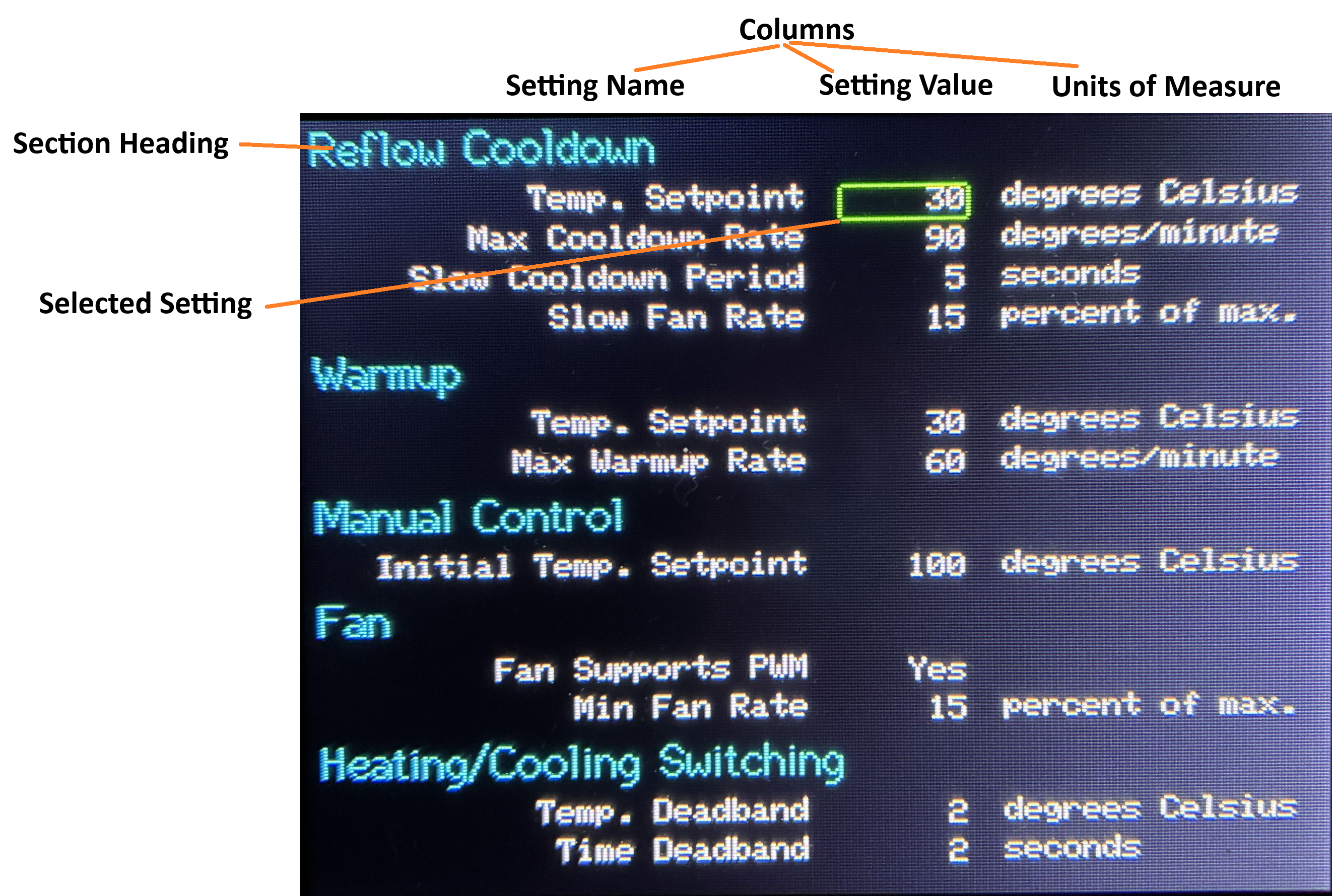
System
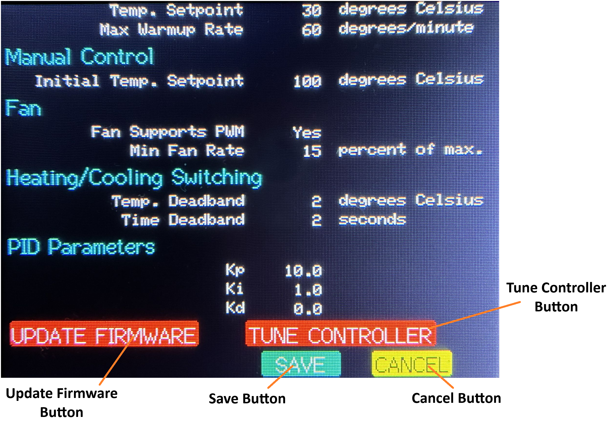
This screen allows you to modify all of the configuration settings associated with operation of the hotplate. There are also buttons to initiate uploading of new firmware and tuning of the PID temperature controller.
The system settings are divided into categories, with each category identified by a Section Heading. Under the headings, are 3 columns displaying the Setting Name, Value and Units of Measure (if any). The currently selected setting is highlighted by a box around the value. As usual, you Press on the selected setting in order to modify it. Rotate the knob to change the value and then Press a second time to complete the change.
There are too many settings to display on a single screen, so the screen will scroll when you "go off" the bottom or top of the screen. The screen wraps around at the top and bottom, so you can (for example) go backwards from the first setting to display the Save and Cancel buttons that are at the bottom of the System screen.
| Screen Element | Description |
|---|---|
| REFLOW COOLDOWN Heading | Settings associated with the Cooldown stage of a reflow operation. |
| Temp. Setpoint | The temperature to which the hotplate should be cooled before the reflow operation ends. |
| Max Cooldown Rate | The maximum allowed rate of cooling of the hotplate. |
| Slow Cooldown Period | At the start of Cooldown, how long the fan speed should be kept at a lower rate. This is useful if your cooling fan(s) can blow so hard that ite (they) might actually misalign some parts on the PCB if it came on full blast right away. |
| Slow Fan Rate | Percent of full cooling that should be used during the Slow Cooldown Period. Only useful if your fan(s) is(are) PWM capable. |
| WARMUP Heading | Settings associated with the Warmup mode. |
| Temp. Setpoint | The default target temperature setpoint for a Warmup operation. This value can also be changed on the Settings screen. |
| Max Warmup Rate | The maximum allowed rate of heating the hotplate when performing a Warmup operation. |
| MANUAL CONTROL Heading | Settings associated with the Manual Control mode. |
| Initial Temp. Setpoint | The default starting temperature setpoint for Manual Control. This value can also be changed on the Settings screen. |
| FAN Heading | Settings associated with operation of the fan. |
| Fan Supports PWM | Indicates whether the fan(s) is(are) PWM capable. NOTE that this setting currently has no effect. |
| Min Fan Rate | Indicates the percent of full flow that the fan produces when it first turns on. The fan I used, for example, cannot be stopped using the PWM signal. It comes on at some minimum rate when power is applied even if the PWM signal is 0. |
| HEATING/COOLING SWITCHING Heading | Settings associated with alternating between heating and cooling of the hotplate. These settings are intended to prevent the controller from rapidly cycling between using the SSR and the fan. |
| Temp. Deadband | Number of degrees that the measured temperature must be offset from the temperature setpoint before the controller will switch between heating and cooling. |
| Time Deadband | Number of consecutive seconds that the measured temperature must be outside the Temperature Deadband before the controller will switch between heating and cooling. |
| PID PARAMETERS Heading | Settings that control responsiveness and stability of the temperature controller. |
| Kp | Proportional tuning parameter of the controller. |
| Ki | Integral tuning parameter of the controller. |
| Kd | Derivative tuning parameter of the controller. |
| Update Firmware Button | Long Press to initiate a firmware update operation. The Firmware Update screen will be displayed. NOTE that any unsaved settings will be lost because the controller is reset to start the firmware update operation - whether the update is completed or not. That is why a Long Press is required. |
| Tune Controller Button | Press to begin tuning the temperature controller. Takes you to the Controller Tuning screen. |
| Save Button | Long Press to save the settings (they are stored in the EEPROM of the ESP32). Once the settings have been saved, the controller returns to the Settings screen. |
| Cancel Button | Long Press to cancel any changes made through the System screen and restore the values that were in effect before the screen was entered. The controller returns to the Settings screen. NOTE this means that the values of the Warmup and Manual Control setpoints will be reset to what was entered on the Settings screen, if either of these values was modified there. |
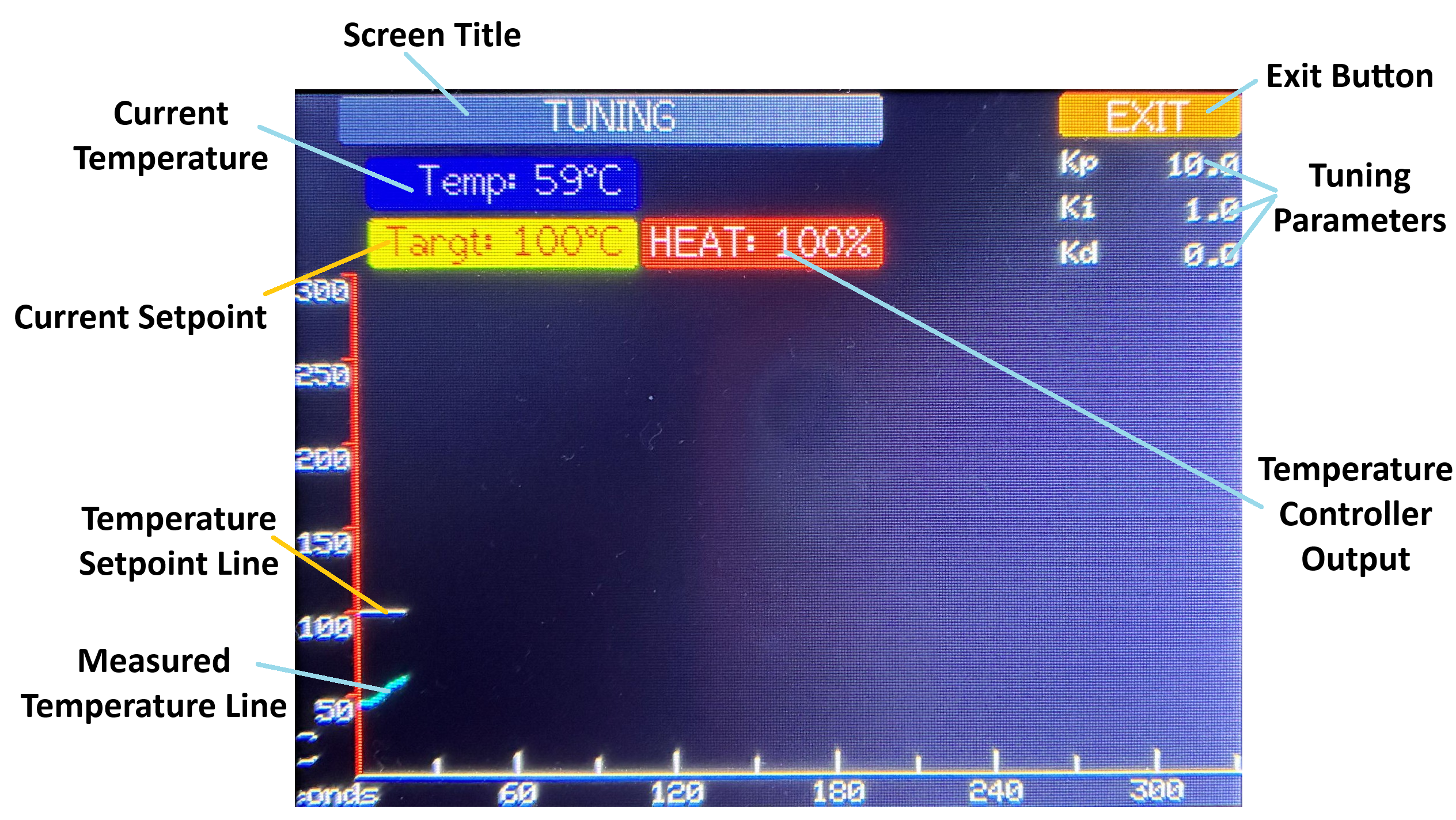
Controller Tuning
This screen is reached from the TUNE CONTROLLER button on the System screen. It operates similarly to the Manual Control screen but also displays and allows you to modify the 3 settings that control how the PID controller responds.
Only manual tuning of the controller is supported. The basic process is:
- Set the temperature setpoint about 10 or more degrees from the current measured temperature (either up or down).
- Observe how the controller responds. How quickly does the measured temperature reach the new setpoint? How much does the temperature bounce around before stabilizing at the setpoint (if ever)?
- Modify one of the tuning parameters based on your understanding of how they operate (you'll have to find a tutorial elsewhere).
- Go back to the first step and test if the response is better or worse. Repeat until you are happy
or you give up in frustration.

If you are using a hotplate similar to the one I used, hopefully the default tuning parameters will work for you "out of the box".
Note
When modifying the tuning parameters, the new value only takes effect once you Press the encoder button a second time, to complete the change of the value.
Warning
The tuning parameters are not saved to EEPROM on this screen. If you want to save the new values, after you exit from the Controller Tuning screen, use the SAVE button on the System screen.
| Screen Element | Description |
|---|---|
| Screen Title | Indicates that the hotplate is in tuning mode. |
| Exit Button | Press to stop tuning of the hotplate temperature and return to the System screen. Note that the heater and fan will both turn off. |
| Current Temperature | Displays the current measured temperature of the hotplate. |
| Tuning Parameters | Displays and allows modification of the 3 temperature controller tuning parameters. |
| Current Setpoint | Displays and allows modification of the current temperature setpoint. |
| Temperature Controller Output | Provides an indication of whether the temperature controller is currently applying heating or cooling to the hotplate. The value indicates the percent of full heating or cooling being called for. The display also switches between a red background, for heating, and blue, for cooling. |
| Temperature Setpoint Line | Plots the temperature setpoint over time. |
| Measured Temperature Line | Plots the measured temperature over time. This provides a visual indication of how quickly and closely the hotplate temperature is matching the desired setpoint. If tuning is carried on for more than 330 seconds (which is the extent of the graph), both lines will wrap back to the left edge of the graph and overwrite the previous values. The markers on the time axis will be updated as they are reached, to reflect the actual elapsed time. |
Firmware Update
Note
The firmware update feature is provided by the AutoConnect library created by Hieromon Ikasamo. Unfortunately, this library increases the size of the program by a significant amount but I have been using this library in projects for years and it was the fastest way I know to add this very useful feature.
This screen is displayed when you press the UPDATE FIRMWARE button on the System screen. In order to perform a firmware update, you must connect to the hotplate access point from the computer where the new firmware is stored.
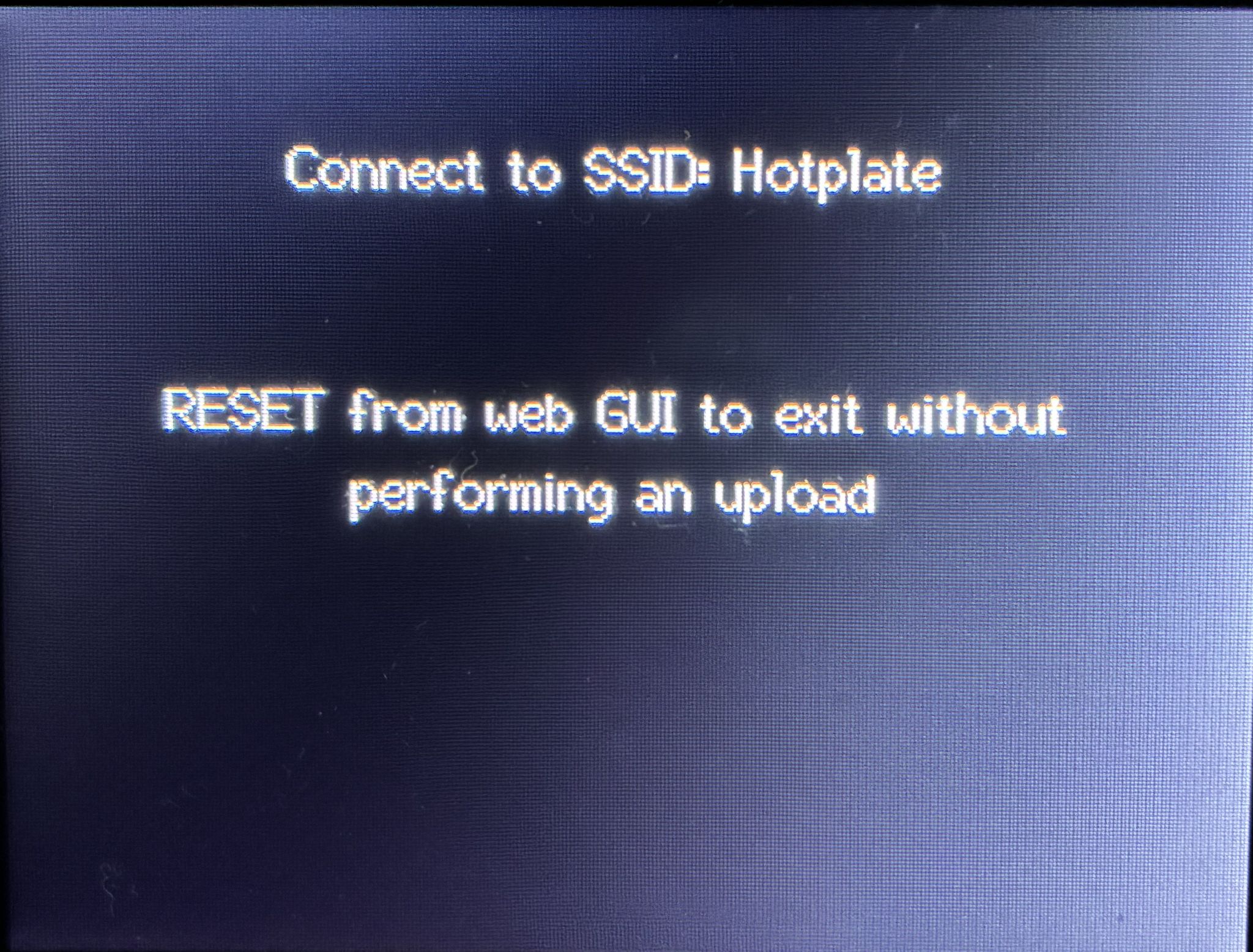
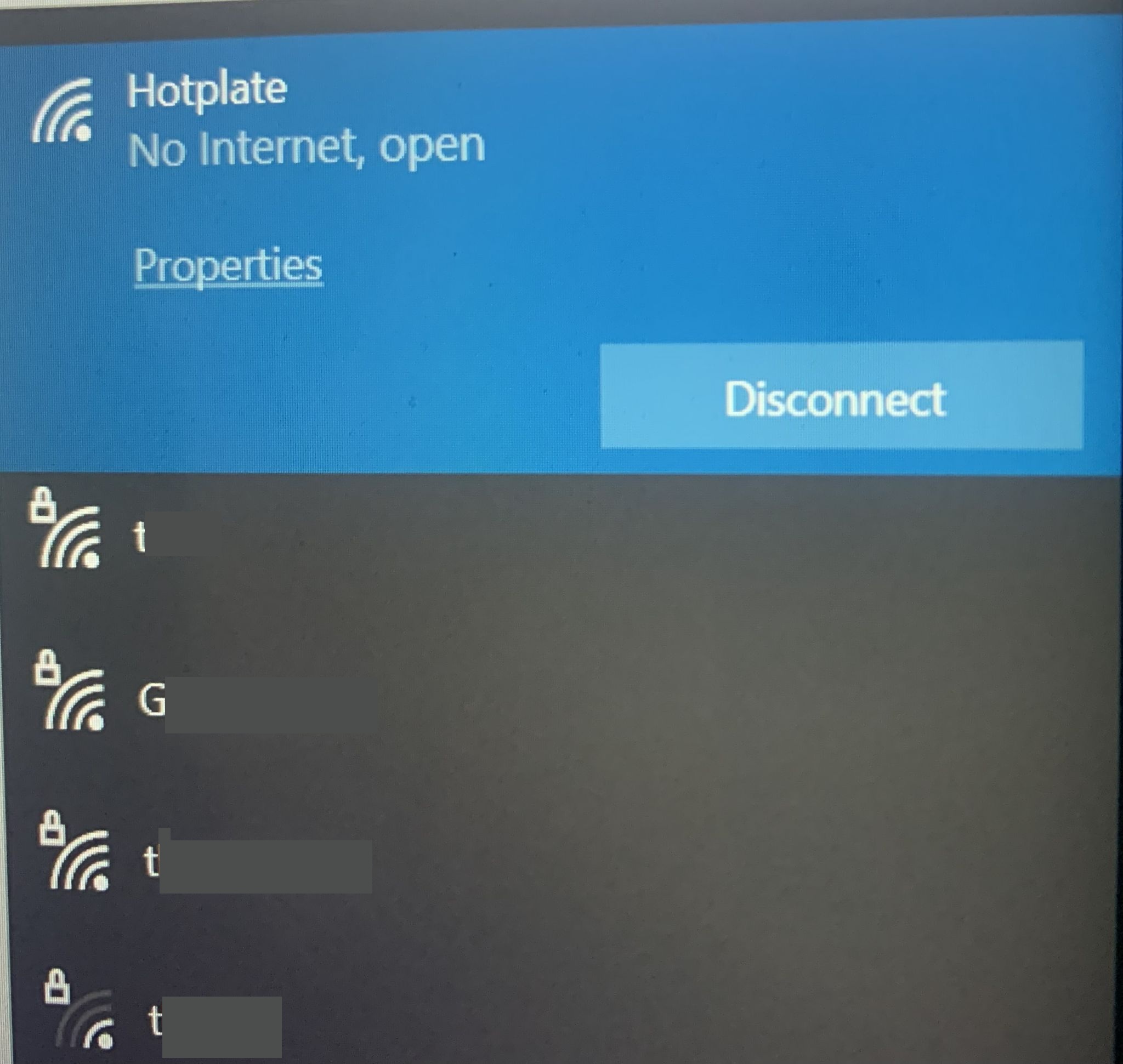
Follow the instructions and connect to the network access point (the SSID) "Hotplate". This access point is only available when the hotplate is in the firmware update mode. (There is no password on the Hotplate SSID because it is only available when you manually start it.)
This screen shot of the network selection screen is taken from a computer running Windows:
Once you have connected to the Hotplate access point, the following screen should automatically appear in your browser window (and the browser should be launched, if necessary):
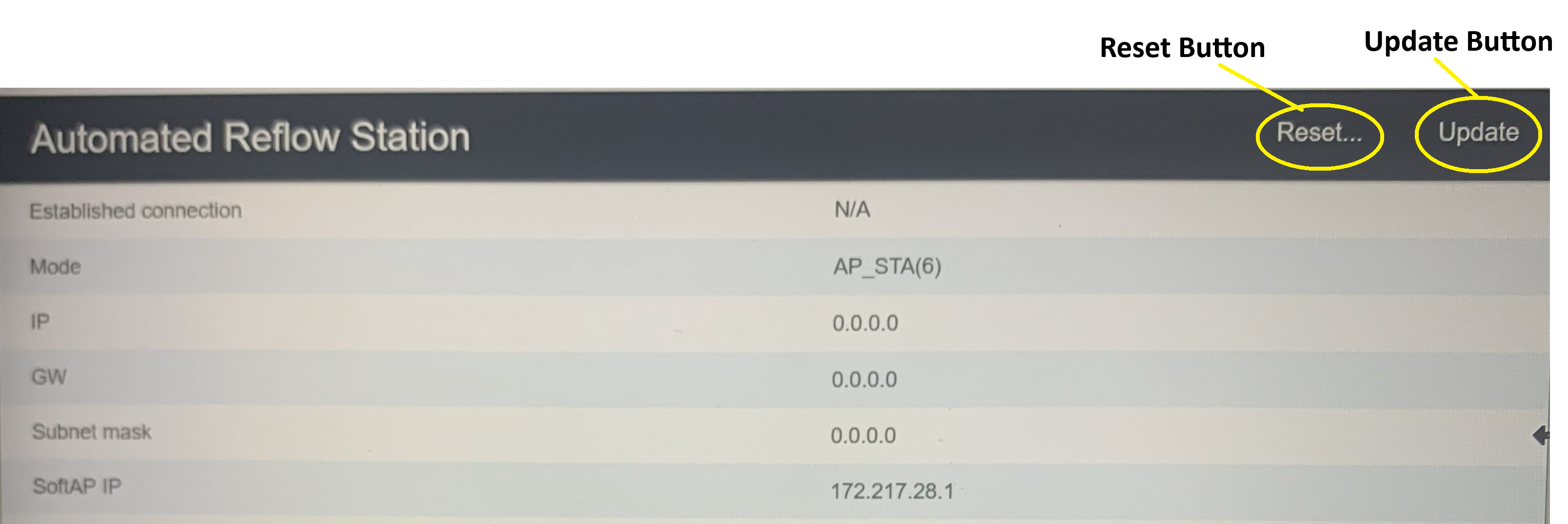
| Screen Element | Description |
|---|---|
| Reset Button | Press this button to reset to cancel the upload operation. The controller will restart at the Welcome screen. |
| Update Button | Press this button to display the Upload screen in the browser. |
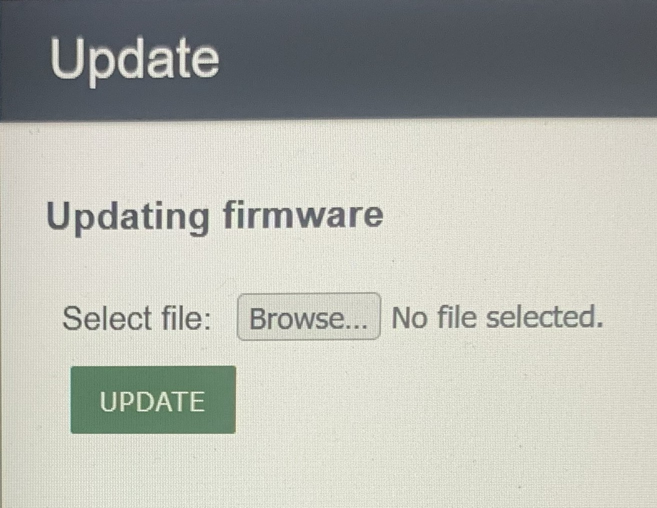
| Screen Element | Description |
|---|---|
| Browse... Button | Press this button to browse the computer and select the new firmware file. |
| Update Button | Press this button to begin the upload process. After the upload is complete, the hotplate controller will be automatically restarted. |